Table of Contents
Macro Language
A video recap of this manual is available on our YouTube channel:
- # - All variables in Macro language started from # symbol and have number (address) in range 0…16000. However variables address higher than 1000 are considered as System Global Variables. It's possible to read an write to Global Variables but User should understand this may change system behavior. Variables in range 1…999 are User space variables. This variables are not changer by CNC control, modifying this variables does not affect system work
- = - Symbol = is ued to assign value to Variable
- Operators
- + addition
- - subtraction
- * multiplication
- / division
- REM modulus operator - remainder
- MOD modulus operator - quotient
- Logic operators
- GT - greater than
- GE - greater or equal than
- LT - less than
- LE - less or equal than
- [] - Square brackets are used to change operation priority (instead of round brackets which are used in g-code language as Comment).
Macros list
“myCNC” has a built-in “Macros list” editor for creating and editing macros. The main functions of the editor are presented below.
Basic window
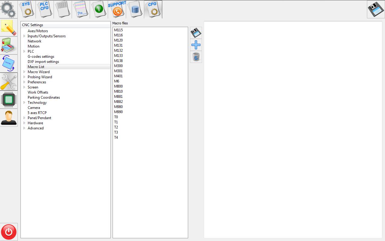
Main functions
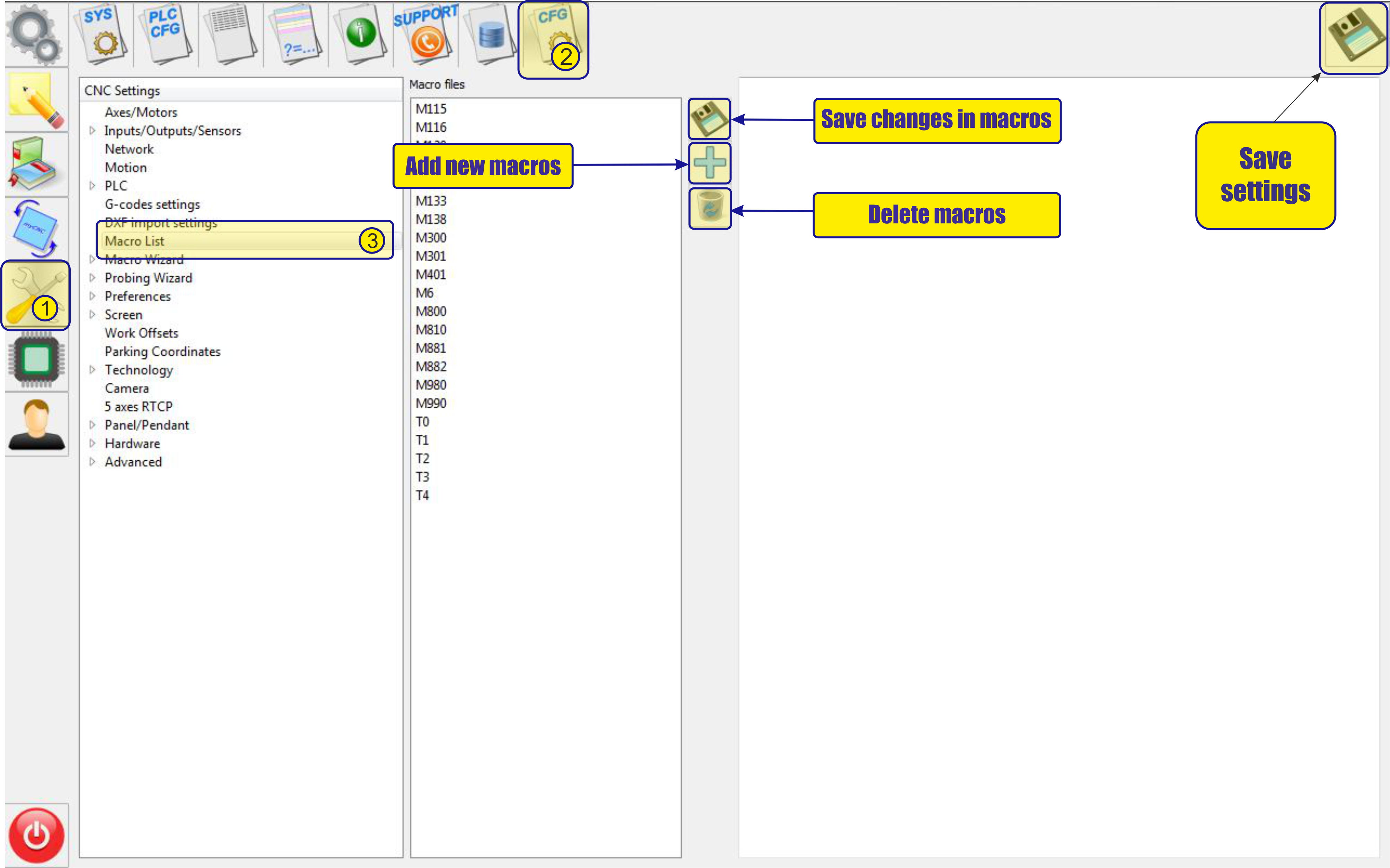
Function "add macros"
To create a macro, you need to click the “+” icon and in the field that appears, enter the corresponding name of the macro.
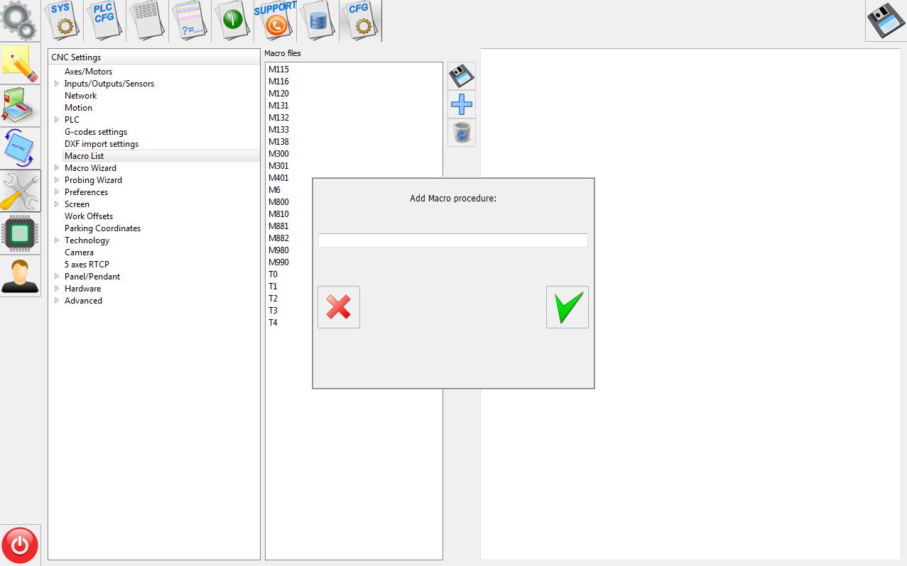 After confirmation of creation, using the “V” icon, the macro will appear in the list of saved macros.
Below is an example of creating a macro named “M222”.
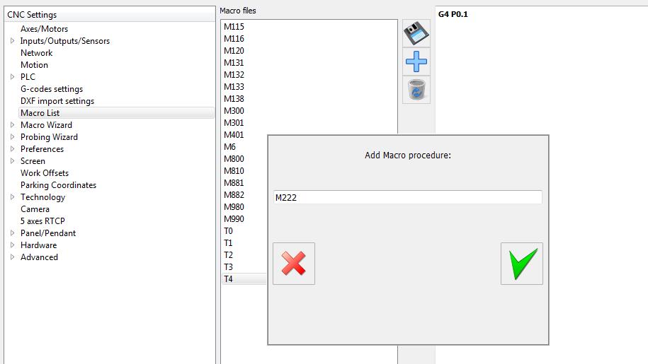
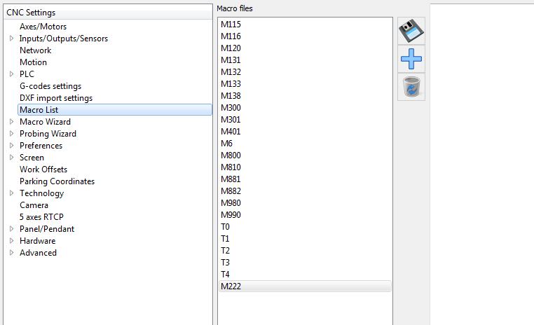
After creating a macro, you can start editing it. To do this, simply select the desired macro and start editing it in the corresponding macro listing window. Below is edit of creating a macro named “M222”.
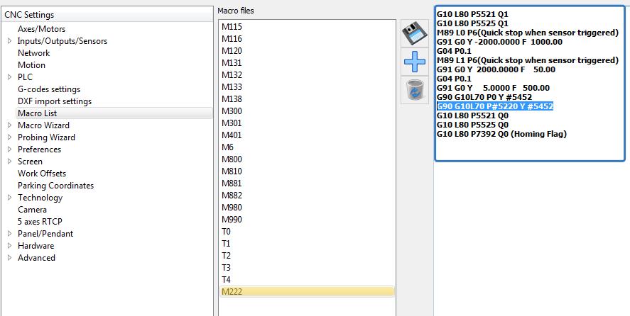 After creating and editing a macro, it must be saved using the “save changes in macro” button
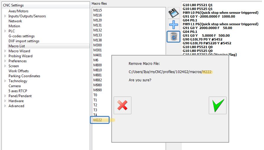
Delete macros
To delete a macro that is not needed, you must select the macro to be deleted and use the function “delete macro”. In the dialog box that appears, you must either confirm or refute the deletion of the macro.
Examples of macros
M120 - Surface measure
- M120.plc
main()
(Surface measure)
(Tool is placed somewhere above the surface sensor)
(Surface Sensor Width is placed into Parameter #5490)

G28.2 Z0.		(save current z position into Register1.Z (value with Z doesn't matter))
G53 G38.2 Z-10.		(move down to z=-10., stop while sensor is pressed)
G10 L70 P1 Z#5490	(set current work position as Z=0 (with offset depends on tool sensor width))
G28.5 Z0.		(return back to saved Z position in Register1.Z (value with Z doesn't matter))
M140 - Homing for X coordinat
- M140.plc
main()
G10 L80 P5521 Q1
G10 L80 P5525 Q1
M88 L1 P19(Soft stop when sensor triggered)
G91 G0 X 15000.0000 F  8000.00
G04 P0.1
M88 L0 P19(Quick stop when sensor triggered)
G91 G0 X -15000.0000 F  8000.00
G04 P0.1
G91 G0 X    20.0000 F   500.00
G90 G10L70 P0 X #5451
G10 L80 P5521 Q0
G10 L80 P5525 Q0
G10 L80 P7391 Q0 (Homing Flag)
Quick note: in system macros (especially in which coordinates are reassigned and/or reset), G0 positioning codes must be used.
Repeat Test
G10 L80 P5521 Q1 (Disable Software Limits)
G10 L80 P5525 Q1 (Disable Hardware Limits)

#10=1 (Initialize register value)

N20

M88 L1 P14(Soft stop when sensor triggered)
G91 G0 Y   10.6 F   600.00 (Move to sensor)
G04 P0.2 (Pause)

M220 (Check coordinate, print it)

G90 G0 Y   -10.0000 F   600.00

#10=#10+1 (Increment register)

if [ #10 LT 100 ] 20 (Repeat 100 times)
