Table of Contents
IHC (Initial Height Control)
IHC Software setup
The three most prevalent methods for Initial Height Control of the plasma torch are the following:
- Ohmic Sensor. The ohmic sensor is triggered at the moment the outer casing of the plasma torch touches the working metal - the difference in voltage is registered by a sensor which indicates that the torch is right at the surface of the metal.
- Floating Head. A floating head system uses a spring which presses a button after the torch has come into contact with the work surface, which signals that the torch has touched the metal. It is important to note that this system typically gets triggered only after some additional travel (the machine has to travel a little lower than the torch contact point to compress the spring enough - this must be accounted for).
- Probe Sensor (pneumatic cylinder). Typically, a pneumatic system lowers down some sort of a probe sensor which will be set up lower than the plasma torch. The machine travels downwards until the probe is triggered, and then the probe is pulled back up as to not interfere with the cutting process.
The myCNC IHC system allows the user to work with all three of these systems, with the setup process being similar between all of them. Despite mechanical differences in these IHC systems, the way the controller performs the IHC procedure makes the IHC setup fairly universal.
Two out of three systems listed above (the Ohmic and the Probe Sensor) require the IHC system to only work before the cutting process starts. For the ohmic sensor, this is due to the fact that it must only register the voltage drops during the IHC process, while the probe sensor needs to be brought down/up before the cutting process as to not interfere with it. Therefore, these two systems require an INPUT from the sensor to the controller - the signal that indicates that contact has been made - and an OUTPUT from the controller to the IHC system housing those sensors, which indicates that these systems must be activated during the IHC phase.
On the other hand, the floating head system simply requires an INPUT to the controller to indicate that the button has been pressed. It does not need to be retracted or turned off when the cutting commences, so no OUTPUT from the controller is needed. Therefore, in order to set up the IHC system within the myCNC software, the user needs to assign at most two connections (or sometimes only one, in the case of the floating head mechanism).
The INPUT sensor will be assigned in the pins.h file (found in Settings > Hardware > PLC > Hardware PLC) as INPUT_IHC, while the OUTPUT connection will be assigned as OUTPUT_PROBE. The pins.h file is explained in the following video:
Then, the sequence will be the following:
- IHC process begins, OUTPUT_PROBE is turned on (enables the ohmic/probe sensors, does nothing if floating head is used)
- The torch begins to travel downwards
- The INPUT_IHC sensor (be it an ohmic sensor, a probe or a floating head) is triggered, indicating to the machine that contact with the working surface has been made
- OUTPUT_PROBE is turned off (disabling the probe/ohmic sensor if those are used), the machine travels a necessary distance up/down, and the rest of the IHC/THC process begins.
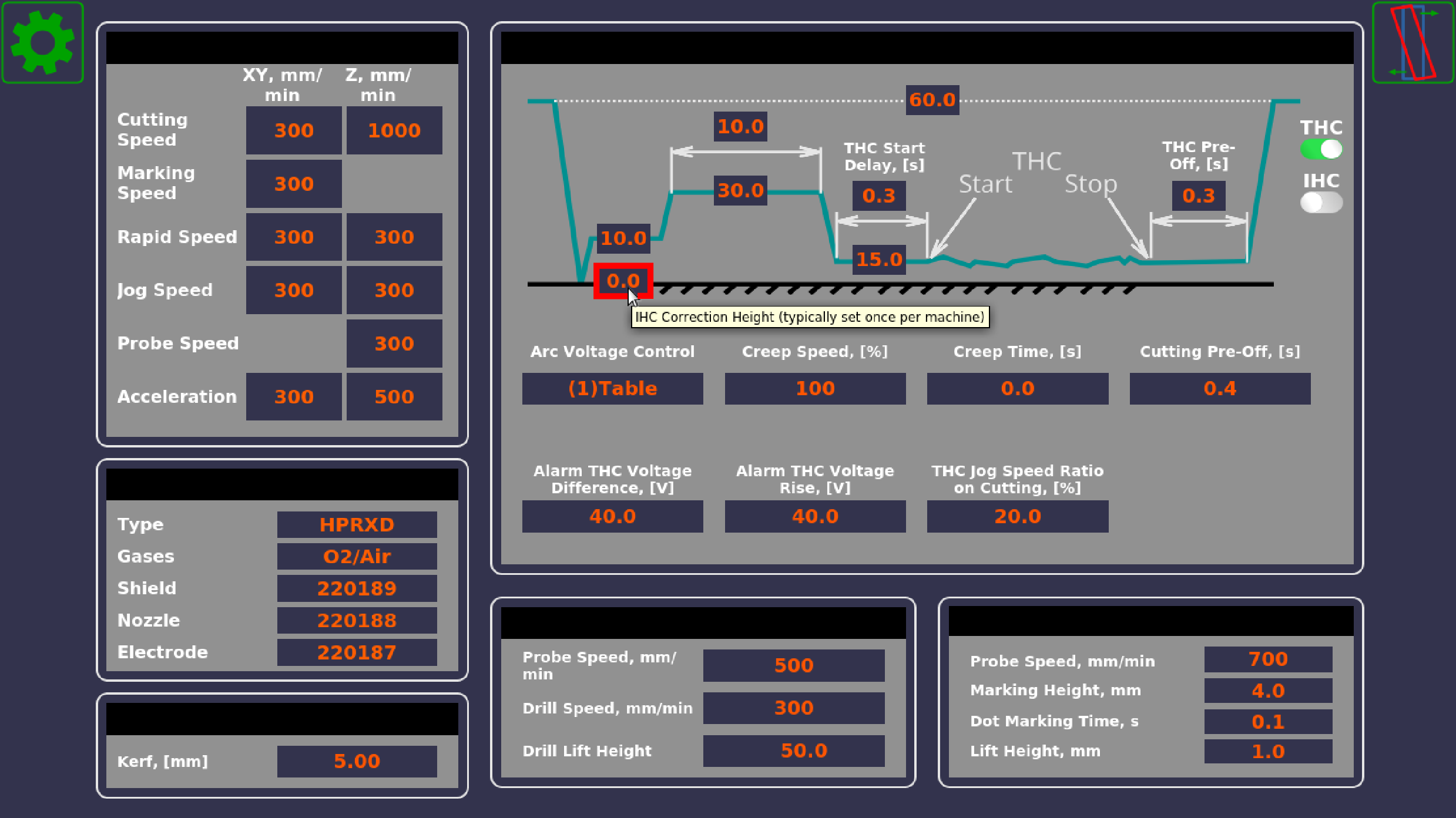
This last step is where the difference between the three different potential systems becomes apparent, as their differences in position Z at which the input sensor is triggered must be accounted for. This is where the IHC Correction Height (found in the User Settings) is used:
(You can read more about the different settings in the diagram above in the THC manual).
This correction height allows the user to account for the machine height at which the IHC Sensor (our INPUT_IHC) gets triggered.
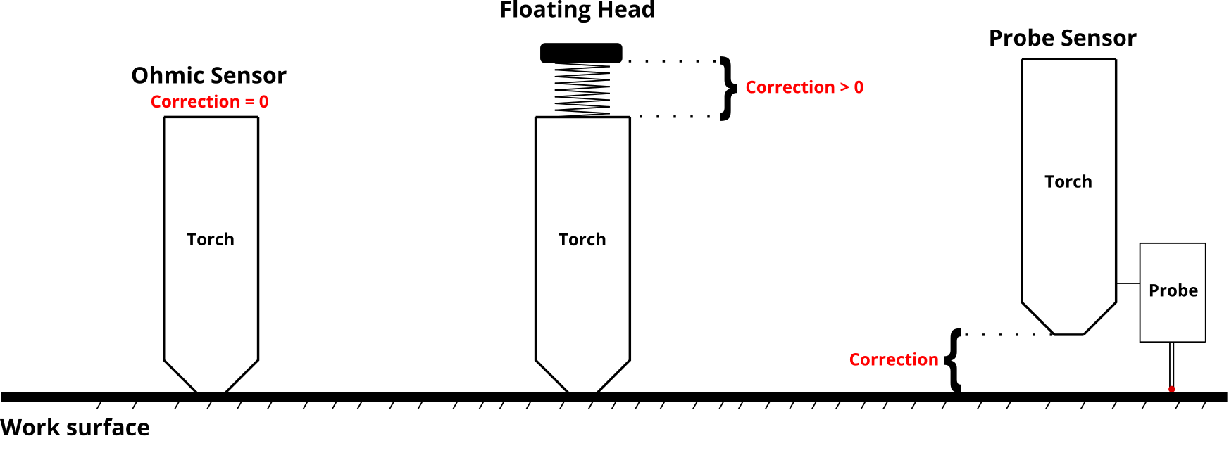
- Ohmic sensor: the sensor gets triggered when the torch tip lines up exactly with the working surface. There is no correction height to account for. IHC Correction Height = 0 (shown in the screenshot above).
- Floating head: the machine continues to push down for some distance after contact has been made - the correction height is always positive or zero (in case of negligible travel). IHC Correction Height >= 0 (for example, 2).
- Probe sensor: the probe is typically lower than the plasma torch - the IHC Correction Height is therefore specified as negative (for example, -2).
Below is a diagram that illustrates the idea behind the IHC Correction Height:
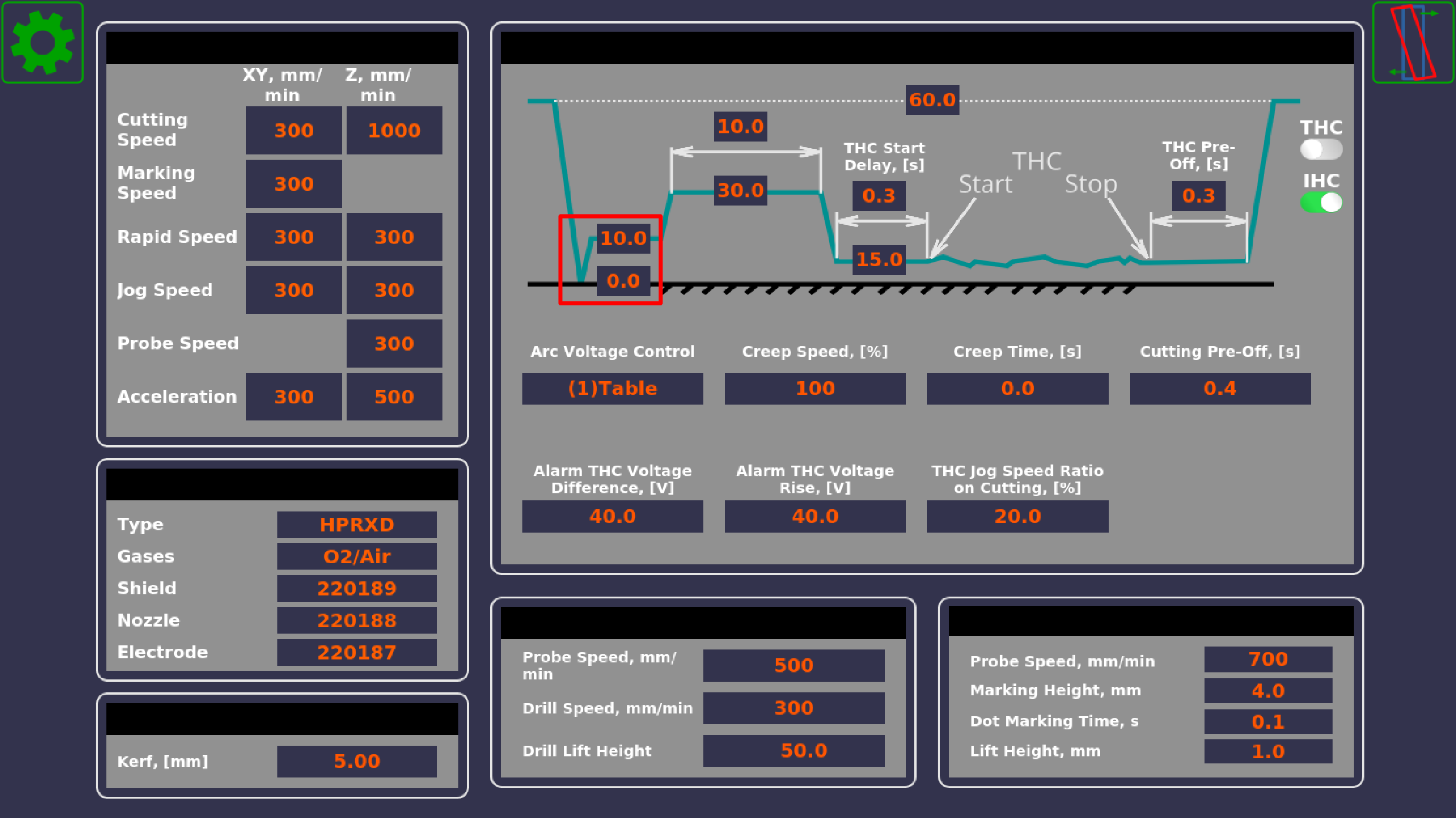
After the contact has been made, the machine will travel up by the IHC Ignition Height + the IHC Correction Height:
If, for example, a pneumatic probe system has been used, the IHC Ignition Height is equal to 6.0, and the IHC Correction Height is equal to 1.0, the system will go up by 7.0 mm after contact with the working surface has been made. It will then wait at this ignition height until it receives the Arc Sensor input, and will then proceed with the pierce and the THC sequence.
IHC and Arc Sensors
NOTE: This section is a cross-post from the MyCNC Plasma Setup Example (X1366P) manual.
In a typical configuration:
- IN0 - Arc Transfer (Arc ON) Sensor from the plasma power source.
- IN1 - Initial Height Control (IHC) Sensor or Probe Sensor - a sensor which triggered when the torch touches the material sheet.
Both inputs should be configured in PLC Builder, in the pins.h file which can be accessed by going to Settings > Config > PLC > Hardware PLC. Either of these can also be re-assigned to other input pins, 0 and 1 have simply been chosen out of convenience to have a default set of connections:
#define INPUT_ARC	0
#define INPUT_IHC	1
The video below shows the steps necessary to set up the IHC/Arc sensors in the X1366P plasma profile:
Necessary steps:
- Connect the Arc and IHC sensors to the control board (can check the port numbers the sensors are connected to in the diagnostics window)
- In Settings > Config > PLC > Hardware PLC > pins.h, locate the INPUT_ARC and INPUT_IHC lines and change the sensor numbers to their correct values if necessary
- Press the Save All, Build All and Send buttons to recompile the PLC procedures on the disk
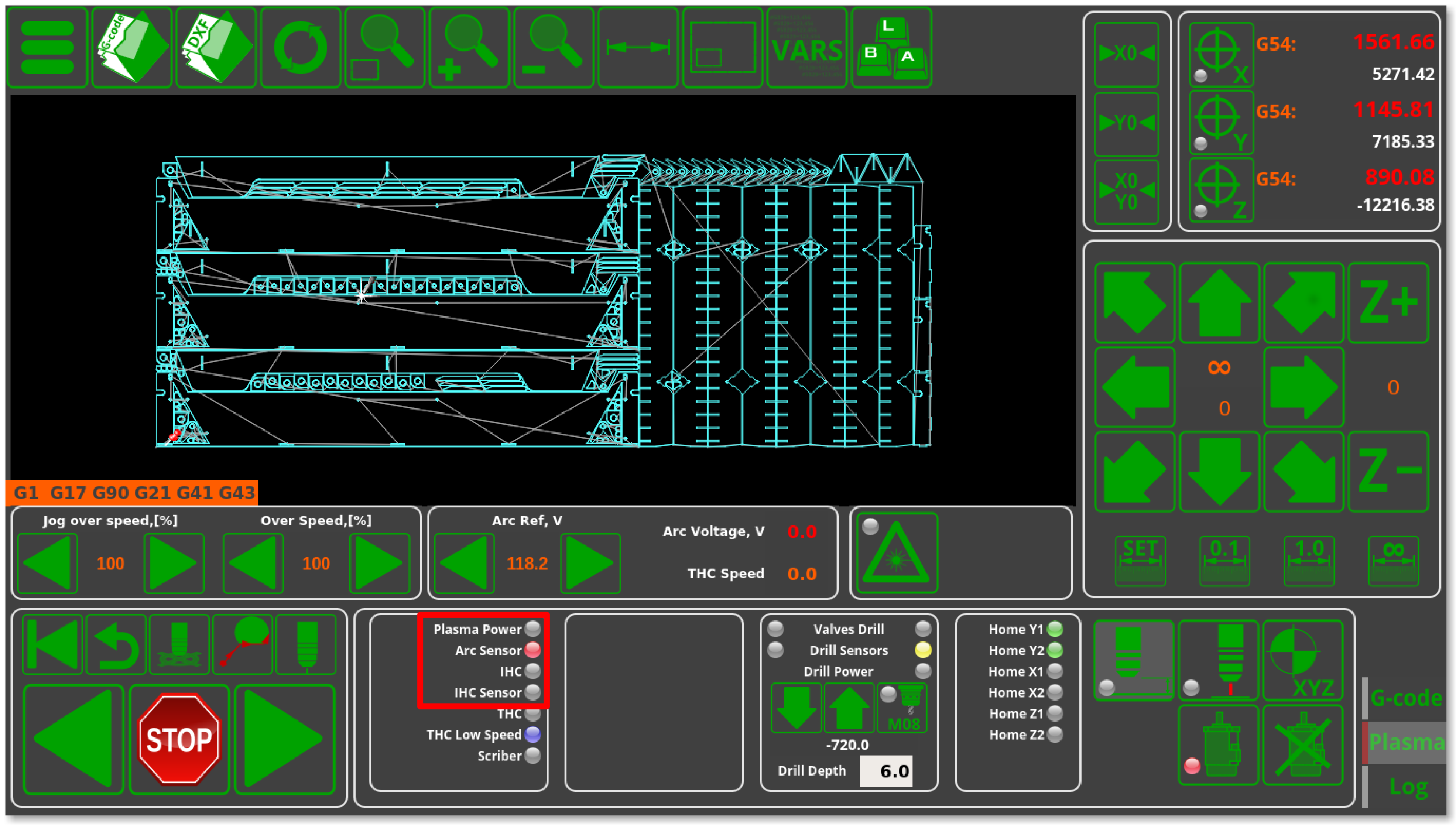
- After recompiling the PLC, you can check that the sensors are operational in the Plasma tab on the main software screen
- Head into the User Settings window from the main menu and select whether you want the IHC to be ON or OFF. If the IHC is OFF, only the Arc Sensor will need to be triggered for the cutting to proceed, while if the IHC is ON, the IHC Sensor will have to be activated before the cutting process begins.
- The system is now set to recognize the sensors that will be used to begin the cutting process. The IHC sensor MUST be activated before the system will initiate the cut (on the initial lowering of the plasma torch).
The following video illustrates the Initial Height Control process that takes place as the program begins to run:
The sequence will be the following:
- The torch will move down until the IHC Sensor is triggered
- After this, the torch will rise by the defined IHC Ignition Height above the point of contact between the metal and the IHC Sensor and will wait for the arc sensor to be activated
- After the Arc Sensor is activated, the torch goes up to the IHC Pierce Height and stays at that height for the Pierce Time
- After the Pierce Time has passed, the torch will go down to the Cutting Height and begin the THC process.


