Table of Contents
MyCNC Pulse Width Setup
- In myCNC software, navigate to Settings
- Open the Hardware tab
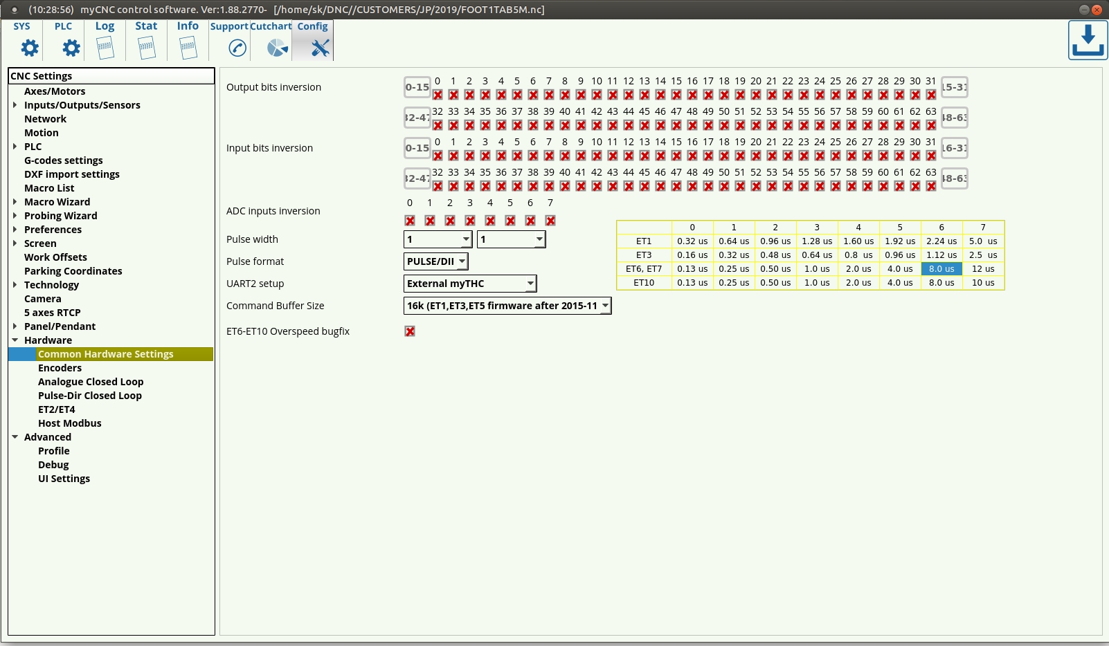
- Open the Common Hardware Settings tab. The following GUI will be presented:
- Select the appropriate Pulse Width
Selecting the Appropriate Pulse Width for your motor
A common procedure required for proper motor operation is selecting the appropriate pulse width for the signal going from the controller to the step/servo motor on the CNC machine. A minimum pulse width is usually noted by the motor manufacturer so as to ensure that the motor can register the signals going to it from the controller (if the pulse width is lower, then the motor cannot “see” the impulse being sent from the controller to the machine).
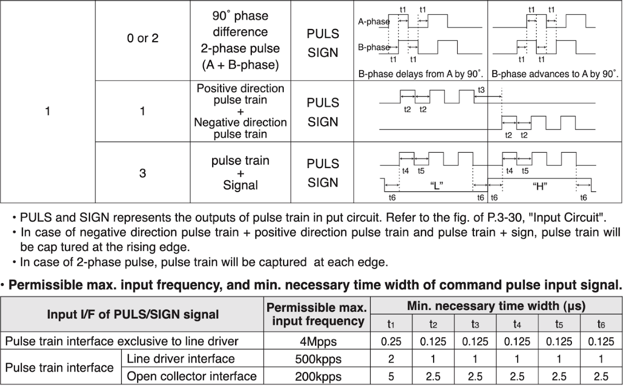
As seen in the following instructions from Panasonic's MINAS A5-series AC Servo Motor & Driver, the pulses have to have a minimum width for the machine to register the signal, ranging from 0.25 to 0.5 μs for the pulse width of the 4 Mpps input and from 5 to 10 μs for the 500 kpps input (obtained as being double of t1 in the charts):
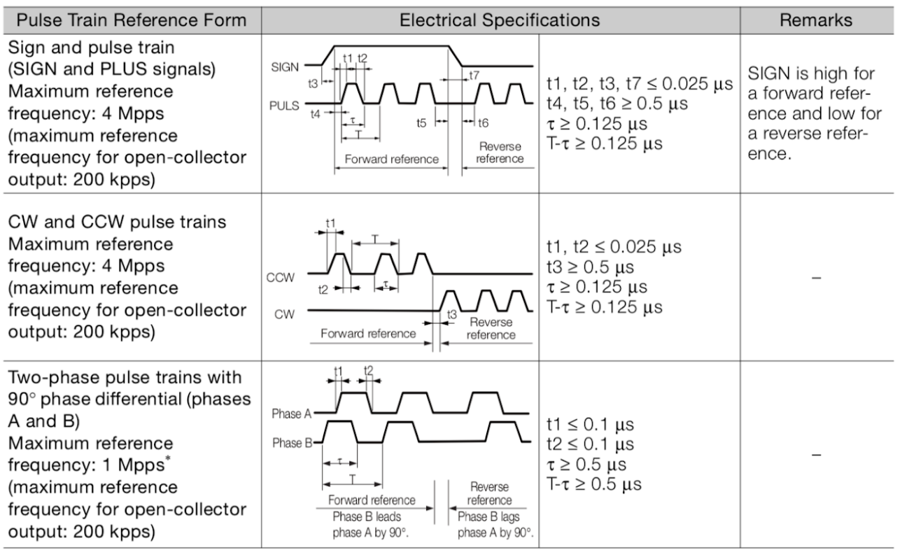
As another example, the Yaskawa's E-7-Series AC Servo Drive also imposes a similar constraint on the minimum widths. The τ in the graph corresponds to the width of the impulse itself, while the T corresponds to the entire period of the signal. The manual advises a minimum τ-T of 0.125 μs to 0.5 μs, depending on the pulse train setup:
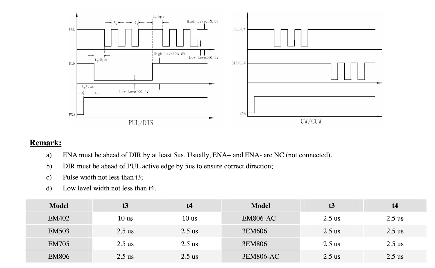
A step motor also requires a minimum pulse width, which is considerably higher than that of a servo motor (around ten to twenty times higher higher when comparing the specs for the Leadshine step motor below to the Yaskawa servo drive):

As such, the pulse impulses sent from the controller to the motor have to have a certain minimum width for the motor to be able to register those signals. However, that signal width also cannot be too large due to the signal overlap that would otherwise occur due to each individual signal interfering with the next one. This is done by ensuring the controller sends impulse signals at a rate that is lower than the period of the impulse at its maximum frequency, resulting in impulse signals that do not interfere with one another while the width of the signal is wide enough for the motor to register the impulse.
These constraints on the minimum and the maximum pulse width create a permissible range of pulse widths for each motor depending on its hardware specifications and the particular speeds it is required to be operated at. Such an optimal pulse width for the controller based on these particular specifications can be calculated.
Pulse Width Calculations
- Choose the speed at which your machine will be moving in [meters / minute]
- Convert the [meters / minute] speed with which the machine will move to the number of [revolutions / second] of the screw/belt/etc based on the [meters / revolution] value of the screw/belt on your machine (this screw/belt value is specific to each hardware setup)
- For example, if the desired [meters / minute] speed of the machine is equal to 5 meters/minute, and the [meters / revolution] value of the screw/belt is 5 millimeters/revolution, the [revolutions / second] value will be calculated as follows:
5 meters/minute ÷ 60 seconds/minute · 1000 millimeters/meter ≈ 80 millimeters/second
80 millimeters/second ÷ 5 millimeters/revolution = 16 revolutions/second
The value for the [revolutions / second] will be equal to 16 revolutions/second
- Locate the minimum [seconds / step] value of your step/servo motor (the minimum time it takes the motor to process each individual impulse). This minimum time should be provided in the motor manual.
- For example, this time T can be equal to 8 · 10^-6 seconds or 8 μs
- Using the [revolutions / second] value and the minimum allowed [seconds / step] value of the motor, calculate how many [steps / revolution] the stepper driver will have to make.
- For example, if the minimum allowable value for the motor is 8 μs/step (8 · 10^-6 seconds/step), and the machine will produce 16 revolutions/second, then the maximum value for the [steps / revolution] will be calculated as follows:
1 ÷ (16 revolutions/second · 8 · 10^-6 seconds/step) = 7812.5 steps/revolution
The value for the number of [steps / revolution] will be equal to 7812.5 steps/revolution
- As discussed earlier, the value selected on the stepper motor must be equal or smaller than the number of [steps / revolution] obtained from the previous step for the motor to register the signal and function properly.
- For example, if the [steps / revolution] value has been calculated to be 7812.5 steps/revolution, then if the stepper driver allows for 3200, 6400, and 12800 steps/revolution, 6400 steps/revolution will be selected as it is the closest value that's equal to or lower than 7812.5 steps/revolution
- Using the [revolutions / second] value and the updated stepper driver [steps / revolution] value, calculate the actual [seconds / step] value of the motor. This actual [seconds / step] value will always be equal or higher than the minimum allowable [seconds / step] value of the motor due to selecting a lower [steps / revolution] value in the previous steps.
- For example, if the [revolutions / second] value was equal to 16 revolutions/second and the stepper driver [steps / revolution] value was equal to 6400 steps/revolution, the actual [seconds / step] value of the motor will be calculated as follows:
1 ÷ (16 revolutions/second · 6400 steps/revolution) = 9.76 · 10^-6 seconds/step = 9.76 μs/step
The value for the [seconds / step] will be equal to 9.76 μs/step.
- The value for the Pulse Width in myCNC software must be set to be equal or to the next closest value that is higher than the actual [seconds / step] value of the motor.
- For example, if the [seconds / step] value was equal to 9.76 μs/step, and an ET6 or an ET7 board was used, 12 μs would be selected from the chart in the Common Hardware Settings tab as it is the closest value that's higher than 9.76 μs
- The 12 μs corresponds to Setting 7 in the chart, thus the Pulse width value should be set to 7 in myCNC software.
- The pulse width setup is now complete
- NOTE: The 3 different values in the Pulse Width line refers to the different motor outputs, in order (for example, the X+, X-, Y+ and Y- axes), and the question of which ones to fill in depends on the motors (and the number of motors) you are using AS WELL AS your controller. These values are typically left to be the same unless different motors are connected to different motor outputs (for example, a stepper/servo combo).
- for ЕТ6, ЕТ7 controllers (older ET7 versions) - value 1 is for the first 4 motor outputs, value 2 is for the next 2 motor outputs
- For ET9 controllers (modern ET7 revisions) - value 1 is for the first 4 motor outputs, value 2 is for the 5th motor output, value 3 is for the 6th motor output. Read more about the ET9 here.
- for ЕТ10 (older ET10 revisions) - all channels are equal (use only value 1, values 2 and 3 are not used)
- For ET12 controllers (modern ET10 revisions) - value 1 is for the first 4 motor outputs, value 2 is for the 5th motor output, value 3 is for the 6th motor output.
- for ЕТ15 - value 1 is for the first 4 motor outputs, value 2 is for the next 2 motor outputs, value 3 is for the last 2 motor outputs
- For example, you'd use values 1 and 2 when using an ET6 or an ET7 controller:


