Table of Contents
Rotary encoder connection and setup
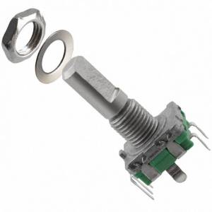
There are 2 types of rotary encoders widely used in pendants and operator panels:
- Simple rotary encoder based on 2 switches. This type of encoders usually generates around 10-40 pulses per revolution (PPR) and used as fancy style “endless multi-turn potentiometer”.
- Industrial style MPG with 100ppr and line driver 5V output
Both types can be connected to myCNC controller and used the operator control panel.
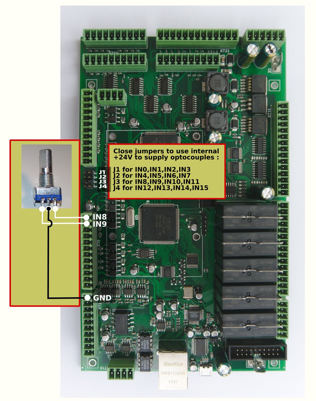
EN11 rotary encoder connection
Encoders can be connected to the galvanic isolated binary inputs. 2 Inputs are used to connect each encoder.
Encoder should be set up in the Config > Inputs/Outputs/Sensors > MPG through binary inputs configuration dialog.
myCNC controllers support up to 4 software encoders defined through binary inputs.
ET7 controller slow encoders setup
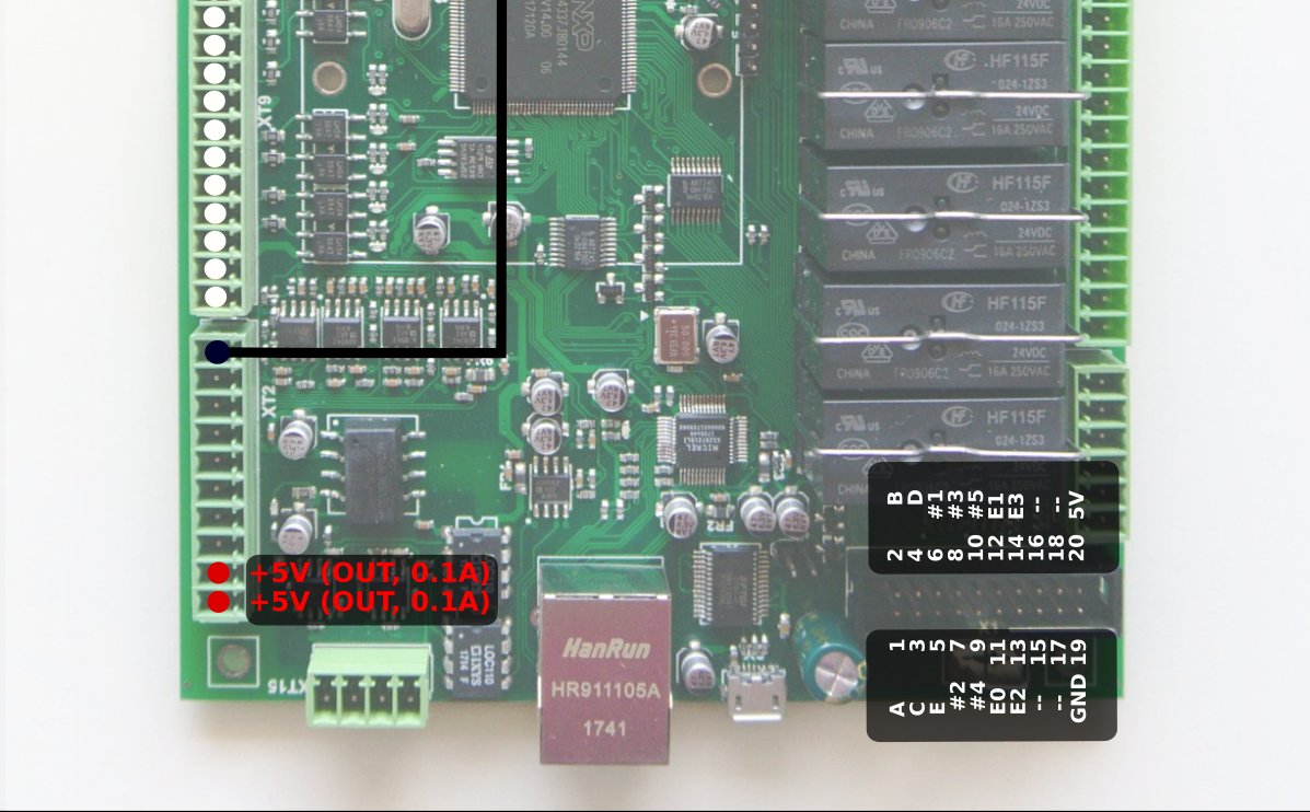
The myCNC-ET7 control board has 2 encoders (Encoder #0, #1) reserved defined permanently. These encoders are supposed to be installed on the ET7-KEY keyboard panel and connected to the 20-pin X4 connector on ET7 control board. It's possible to use external encoders without the ET7-key panel board and to connect those directly to X4 pins 11,12,13,14 and 19. See the table below for more information on the ET7 X4 pinout table:
| X4 connector to External 25-keys keyboard | ||
|---|---|---|
| Pin# | Name | Comments |
| 11 | E#0 | Binary input #16, En#0 A |
| 12 | E#1 | Binary input #17, En#0 B |
| 13 | E#2 | Binary input #18, En#1 A |
| 14 | E#3 | Binary input #19, En#1 B |
| 19 | GND |
These pins are actually Binary inputs #16, #17, #18, #19 which are permanently configured as Encoder#0 and Encoder#1 in myCNC-ET7 controller firmware. This is the reason Slow Encoders #0, #1 configuration for ET7 controller in myCNC software is ignored and can be skipped. However, Encoder #2, Encoder#3 can be attached to any or binary inputs and configured accordingly when using the ET7 board.
For all other control boards (ET6, ET10 and ET15), the slow encoders configurations #0-3 are active and can be used by users.
Rotary encoders setup example is shown on a picture below
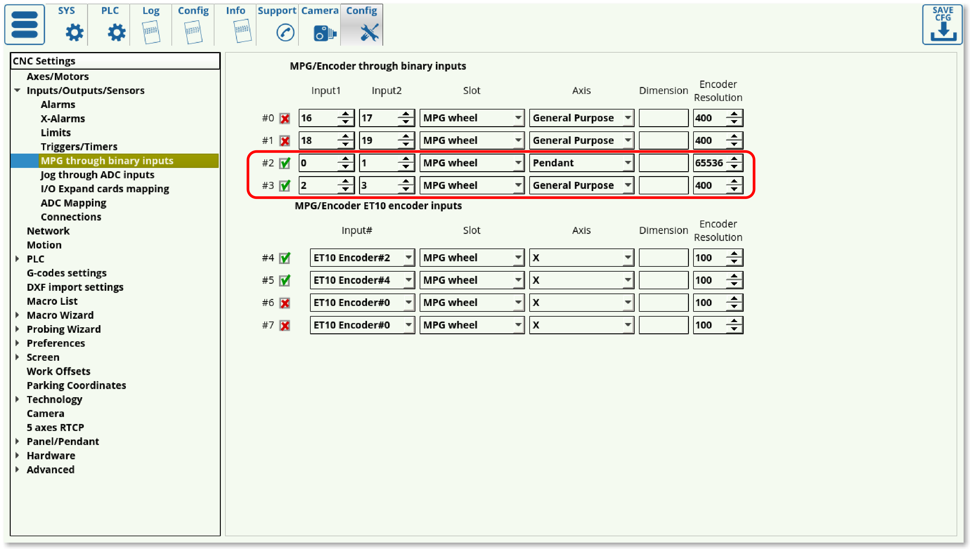 There are 2 encoders attached on Inputs #0,1,2,3 and set up in the dialog.
- Encoder #2 is attached to inputs #0 and #1 and used as a Pendant MPG/Wheel.
- Encoder #3 is attached to inputs #2 and #3 and used as a general purpose encoder.
For ET7 controller, Encoders #0 and #1 are connected to the X4 connector pins 11-14 (or through the ET7-KEY keyboard) and are configured despite being disabled in the myCNC settings window.
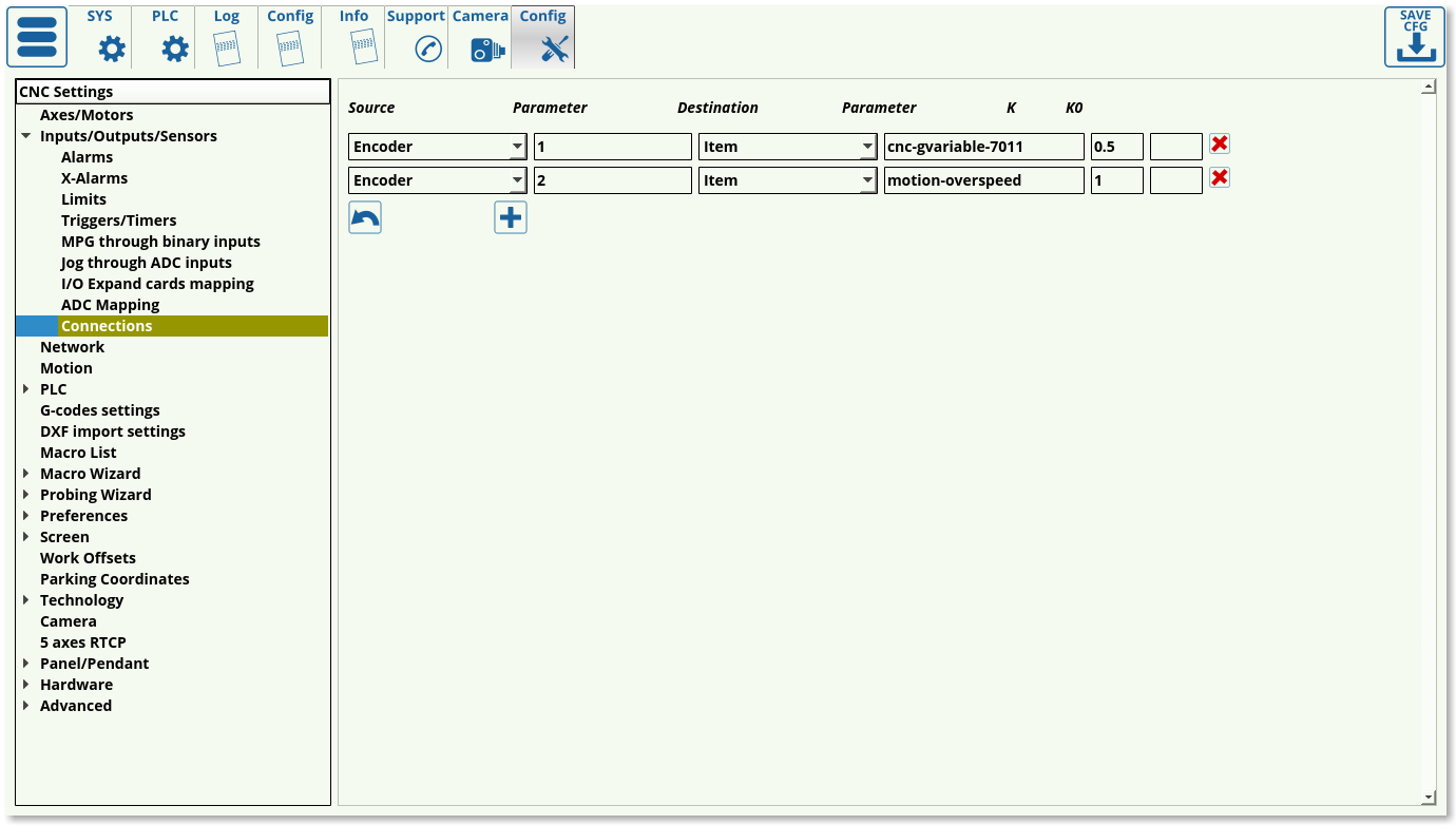
Encoder connection setup through configuration dialog.
A general purpose encoder can be connected to one of the system variables for convenient control.
There is a configuration dialog (described further in the MyCNC Configuration Dialogs manual) which can be used to set up a connection between slow encoder values and CNC parameters.
- Source - a source of connection - can be an Encoder, ADC, input/output pin, PWM, a global variable or other parameters
- Source/Parameter - address of the source. It can be Encoder number, input pin number, global variable address etc
- Destination - destination connection
- Destination/Parameter - destination address
- K - destination ratio. For example, Spindle speed will be increased 100RPM every encoder clicks if “K=100”.
- K0 - destination shift ratio. Usually left to be at 0 (field left to be blank).
On-panel rotary encoders are mostly used to control the following values on-the-fly:
- Overspeed [%] (5-125% safe range)
- THC Arc reference voltage [V] (actually cutting height)
- Spindle speed
A rotary encoder should be connected to the XML configuration Item “motion-overspeed” to control Overspeed [%]
Global variable register 7011 is used to change on-the-fly Cutting height (THC Arc reference voltage)
To change Spindle speed, the XML Item “spindle-default-speed” can be used.
A further selection of commonly used Items can be found in the Common Item List manual.
Obsolete method to establish connection through "cnc-variables.xml" configuration file.
This method was used before the dialog described above was released.
Only used on the old deprecated software versions
The connection assignment can be written directly in the cnc-variables.xml configuration file. For example:
<value name="cnc-connection-item-002"
source="encoder:3"
dest="item:motion-overspeed" >0</value>
- source=“encoder:3” - encoder #3 defined as a source
- dest=“item:motion-overspeed” - motion-overspeed defined as destination
Encoder #3 connected to motion-overspeed variable. Overspeed (%) value will be changed by rotating the encoder.
<value name="cnc-connection-item-003"
source="encoder:2"
dest="item:cnc-gvariable-7012">0</value>
- source=“encoder:2” - encoder #2 defined as a source
- dest=“item:cnc-gvariable-7012” - Global variable for THC Arc Voltage Adjustment value is a destination for the connection
Encoder #2 is connected to the THC Arc voltage adjustment. Adjustment Arc value will be changed to “+1” or “-1” on every encoder click.
Encoder connection troubleshooting
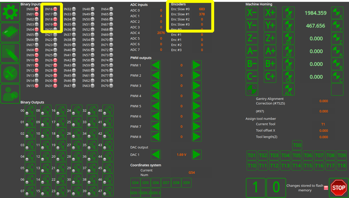
- Go to the Diagnostics page in myCNC software and check which binary input pins the encoder is attached to. To do so, monitor the binary inputs section of the Diagnostics page as you turn the encoder - the relevant input pins should blink as the encoder dial is moved. The input pins #18 and #19 are used in this example, as can be seen in the following picture:

- Check that the “Slow Encoder” values are changed while you turn the encoder.
- Check that the Destination item value has changed while you turn the encoder.
- After the checkup has been complete, reload the program to refresh the settings to the newest configuration.

