Table of Contents
3D Height Mapping
Related articles:
ATTENTION: Height mapping is currently in beta testing.
Height mapping allows to correct the G-code program for abnormalities and slight surface variations of the working material by mapping out the height map of the working material prior to beginning the cutting job. This function is extremely useful when dealing with a working surface which might be oriented imperfectly or may have some abnormalities to it, as well as programs which require a high degree of precision.
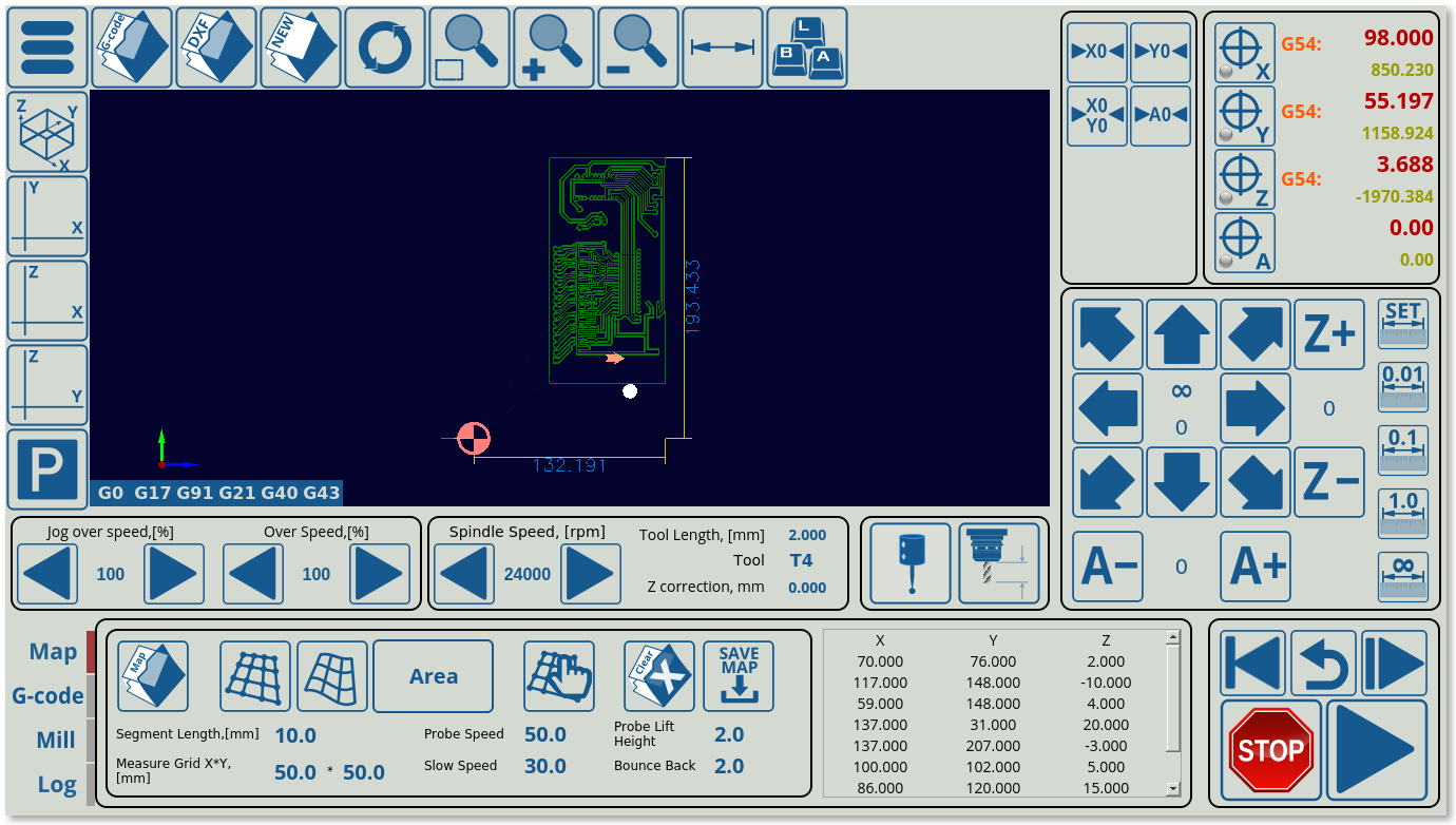
The function is currently being tested for the X1366M, X1366M4 and X1366M6 profiles. Below is an example of the height mapping process in its current beta testing form:
In order to perform the height mapping procedure, do the following:
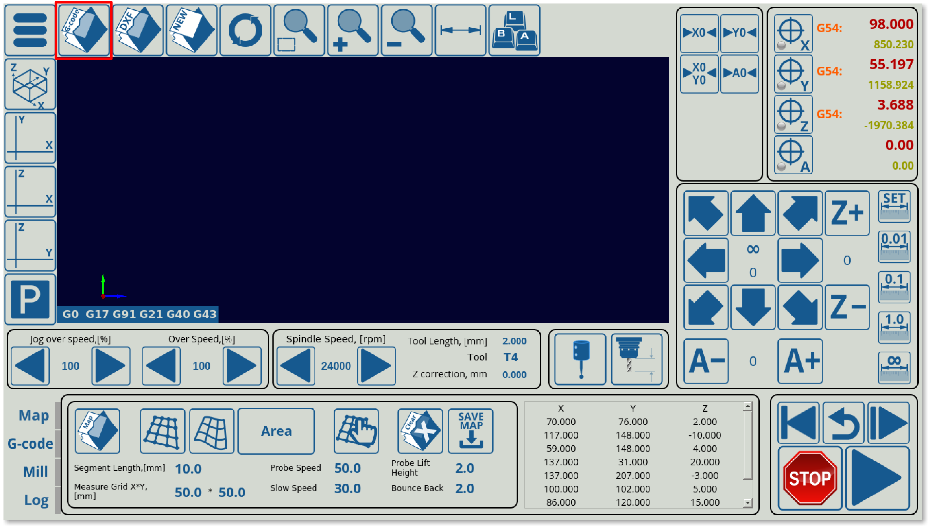
- Open the file that you will want to correct for the material variations
- After opening the file, head to the Map tab on the main screen of myCNC software
- Select your Segment Length and your XY Grid. Increasing segment length and XY grid will result in less probe points being taken.
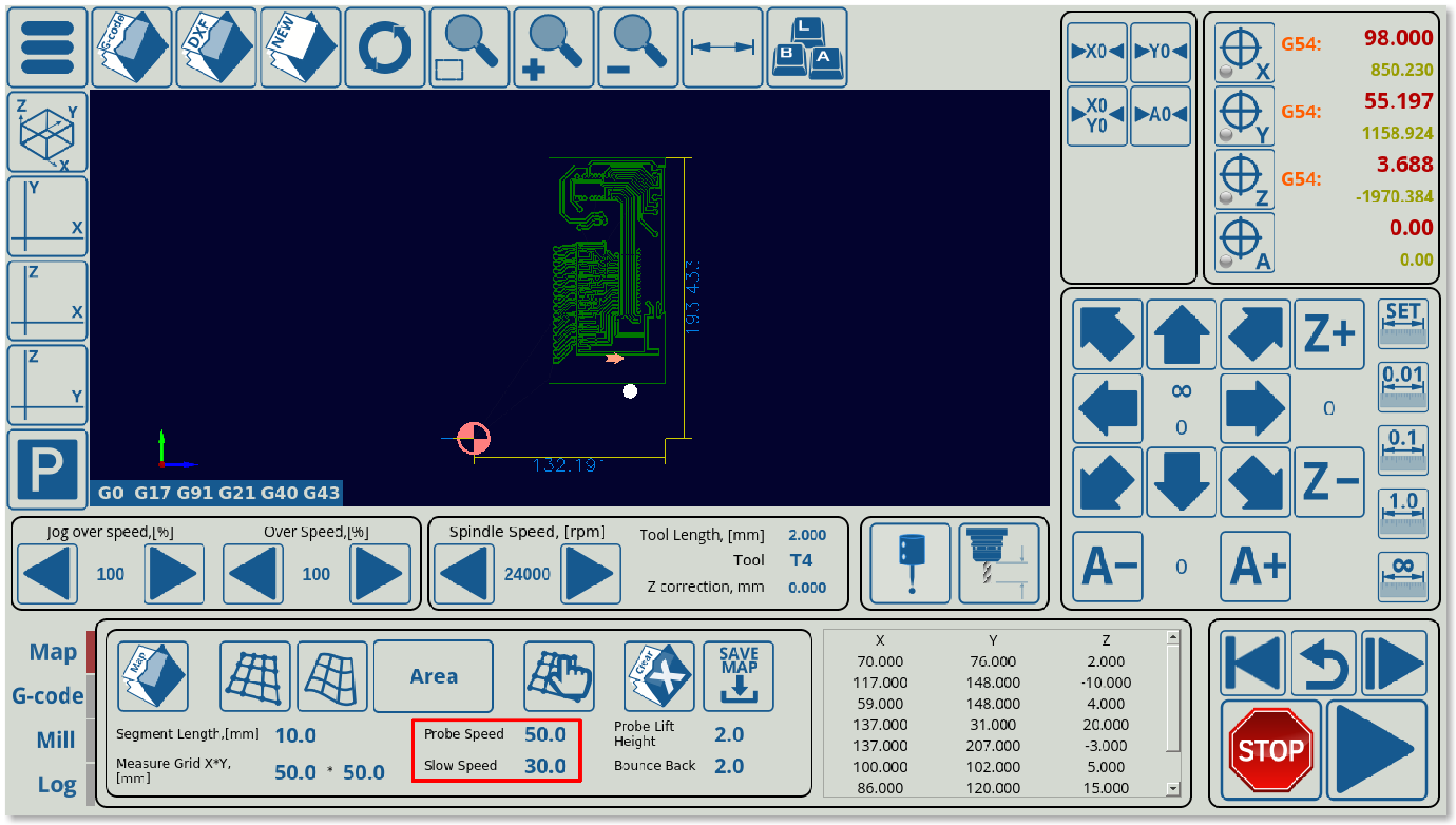
- Select your probe speeds. The probe speed is the speed with which the probe will be moving down from the start of the downward movement to the first contact with the surface. The slow speed is the speed on the rebound, allowing for a more precise measurement of the z-height position on second contact.
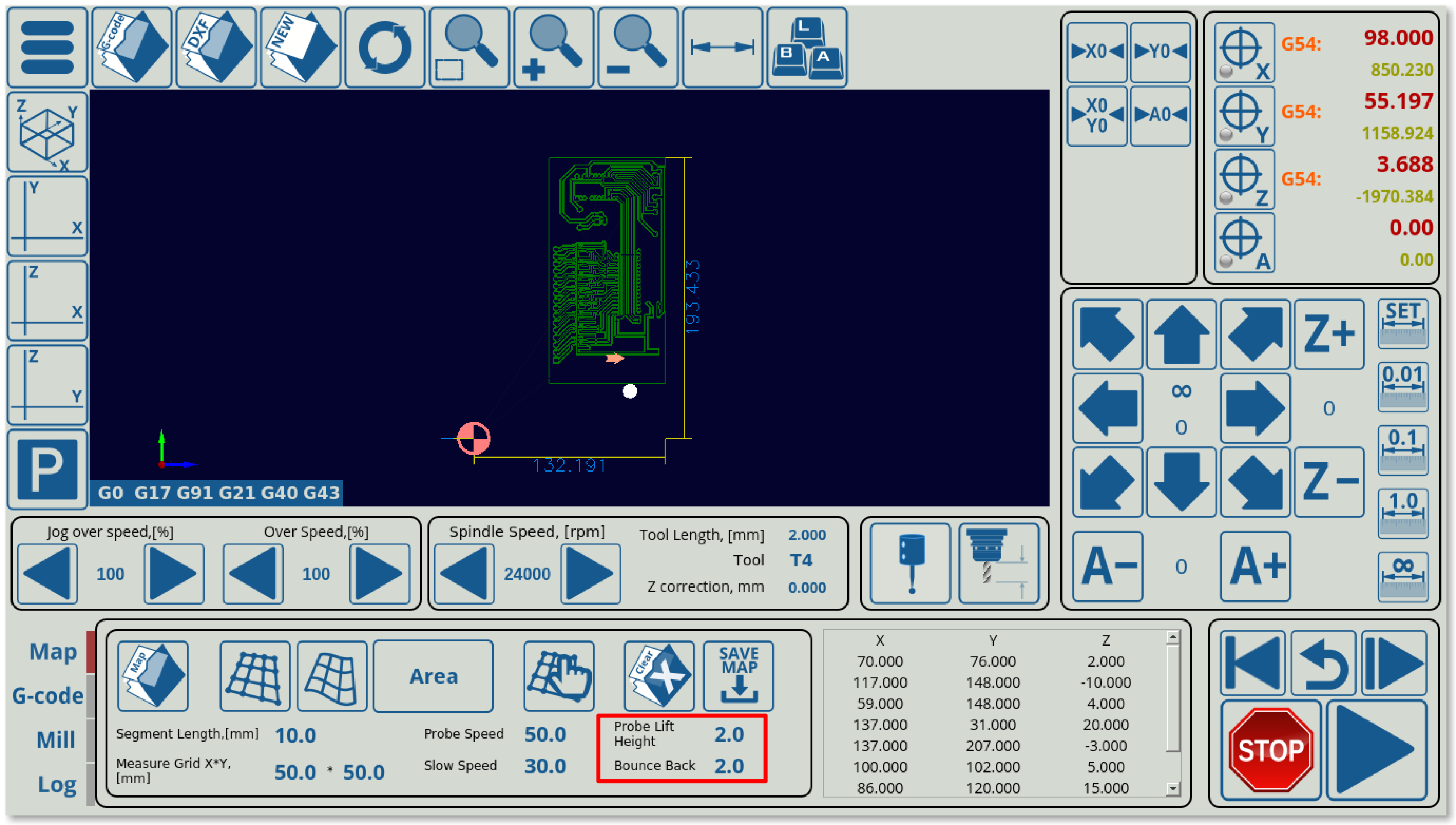
- Select your Lift Height and Bounce Back settings. The Lift Height specifies the z-axis height to which the probe will be lifted between different probing points (safe height). Note that this height is absolute, not relative, so it will raise it TO the position specified in this field in program coordinates, NOT raise the probe BY that amount. The Bounce Back setting specifies the distance the probe retracts after first coming into contact with the working material surface before beginning to move down again.
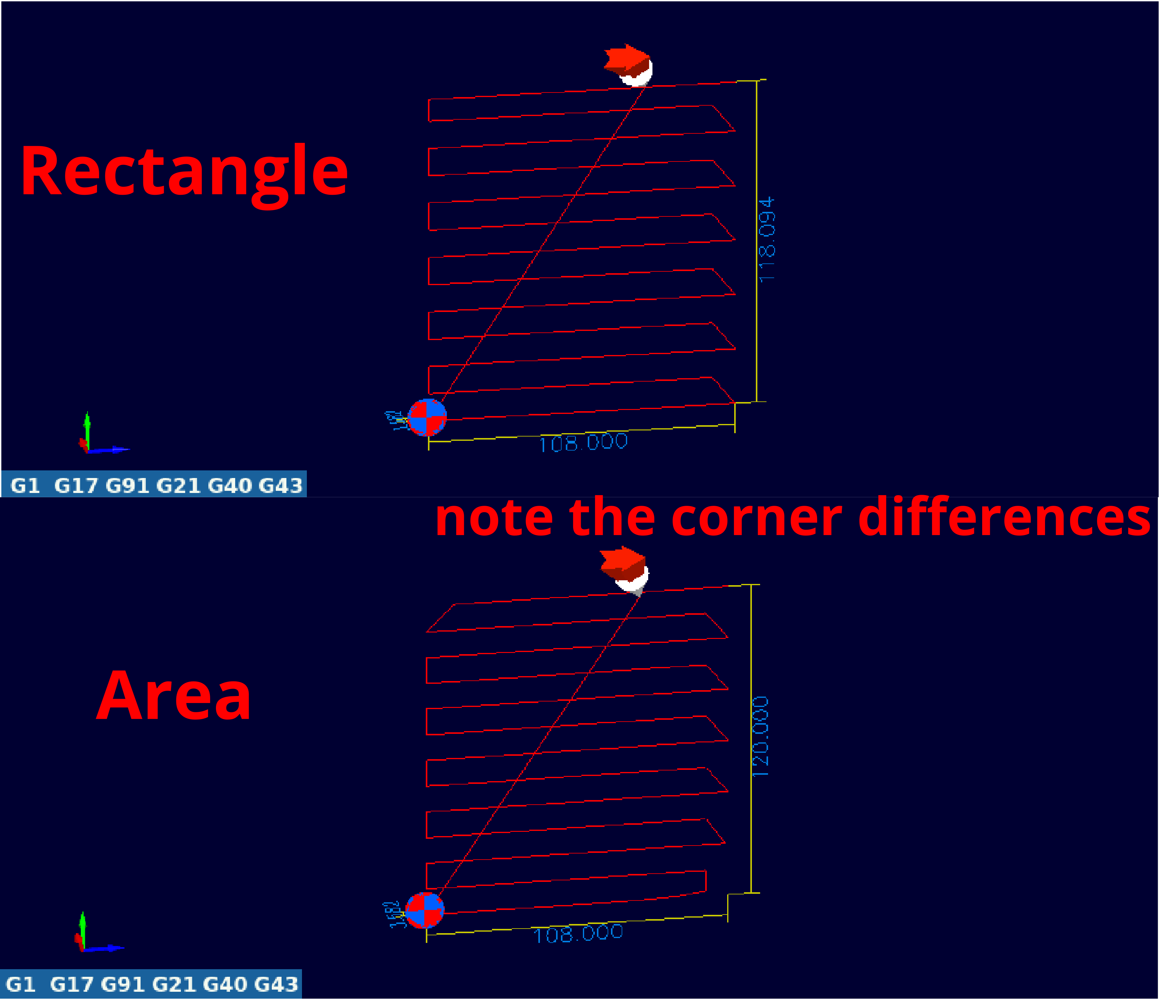
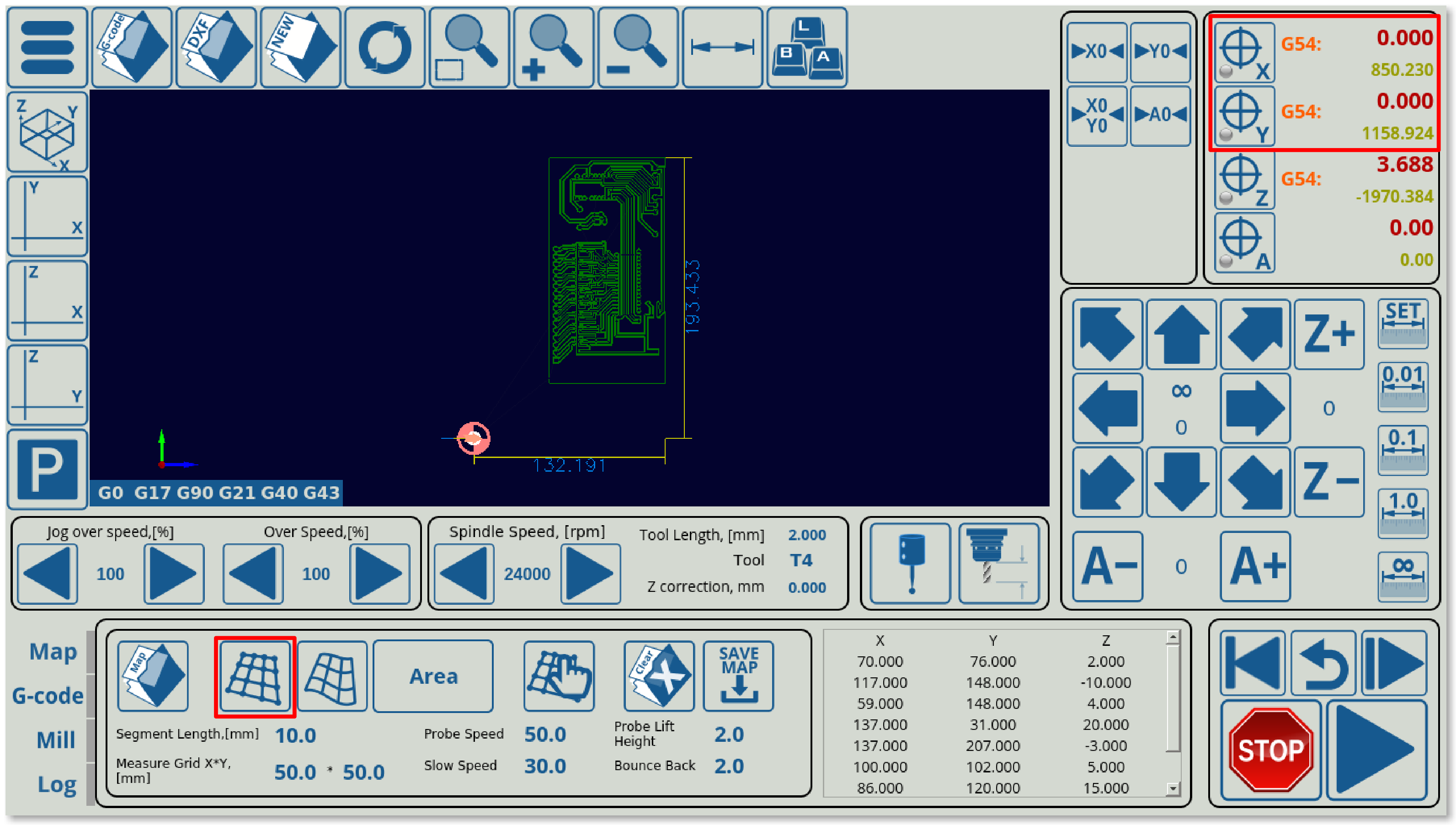
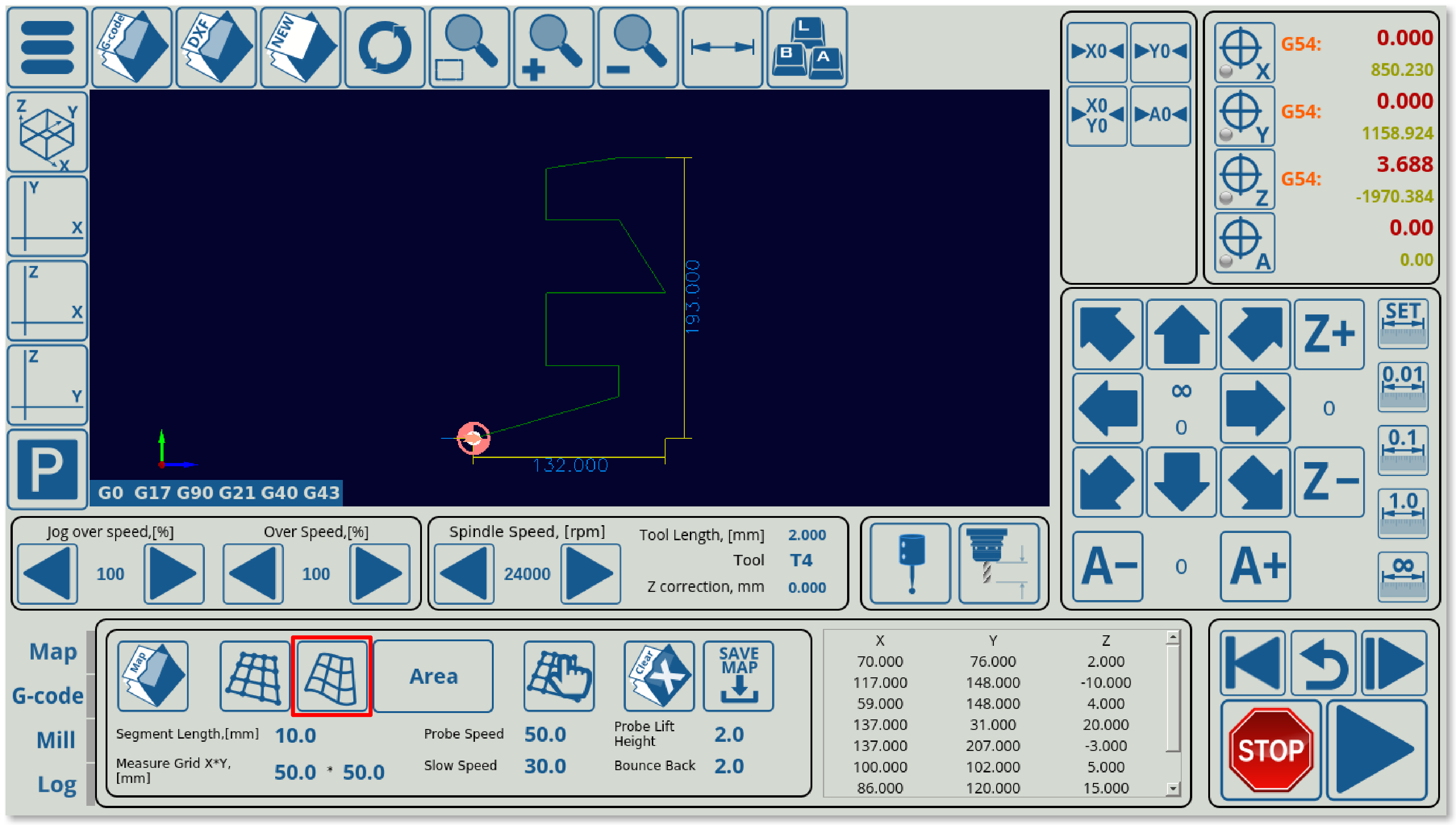
- Select whether you want the material to be probed in a Rectangular or a Fill Area pattern. Generally, either of these methods will give similar results:
- Press the Generate Map button. Note that in order for the map to position itself properly, the X and Y program coordinates must be at zero prior to the map generation step.
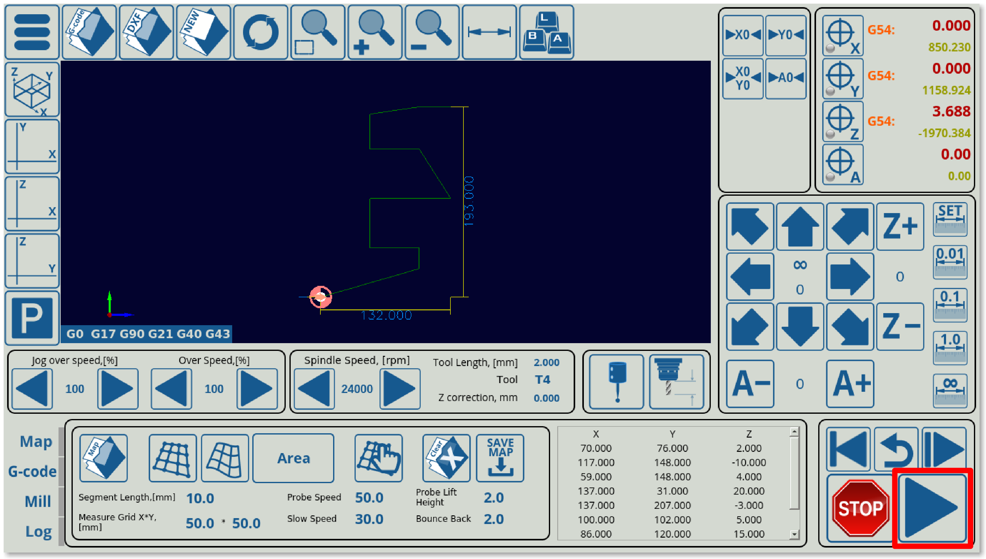
- Press the Run button (this begins the probing process)
- After the probing program has completed running, press the Refresh button in the top ribbon.
- After refreshing the G-code file, press the Apply Map button. The original G-code file that you have loaded in should now be corrected.
- After the file has been corrected for surface level imperfections, you can press the Run button again to begin the actual job.
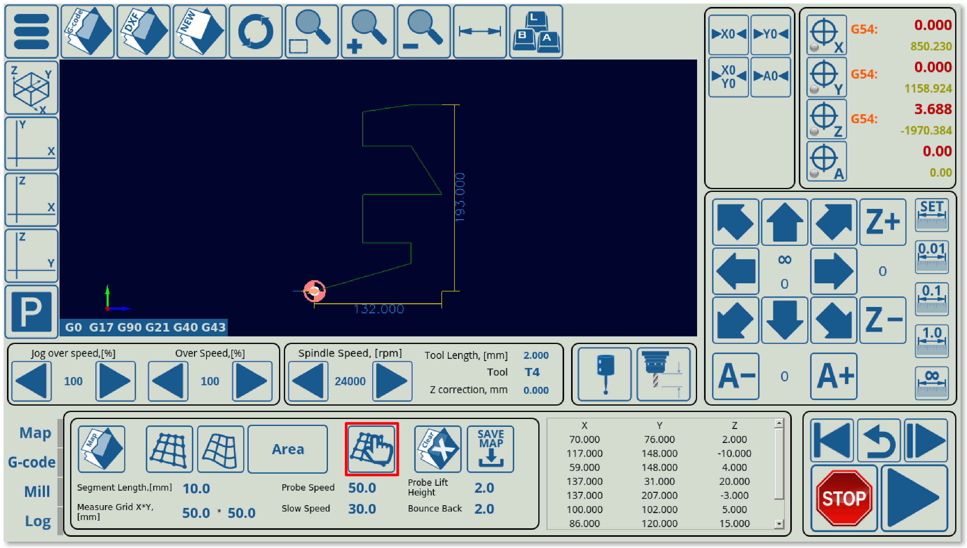
- If you would like to add a manual measurement of a point or a set of points, you can do so by moving the machine to an arbitrary XY location and recording the height there using the Manual Height Probing button. This will add that XYZ point to the existing height array.
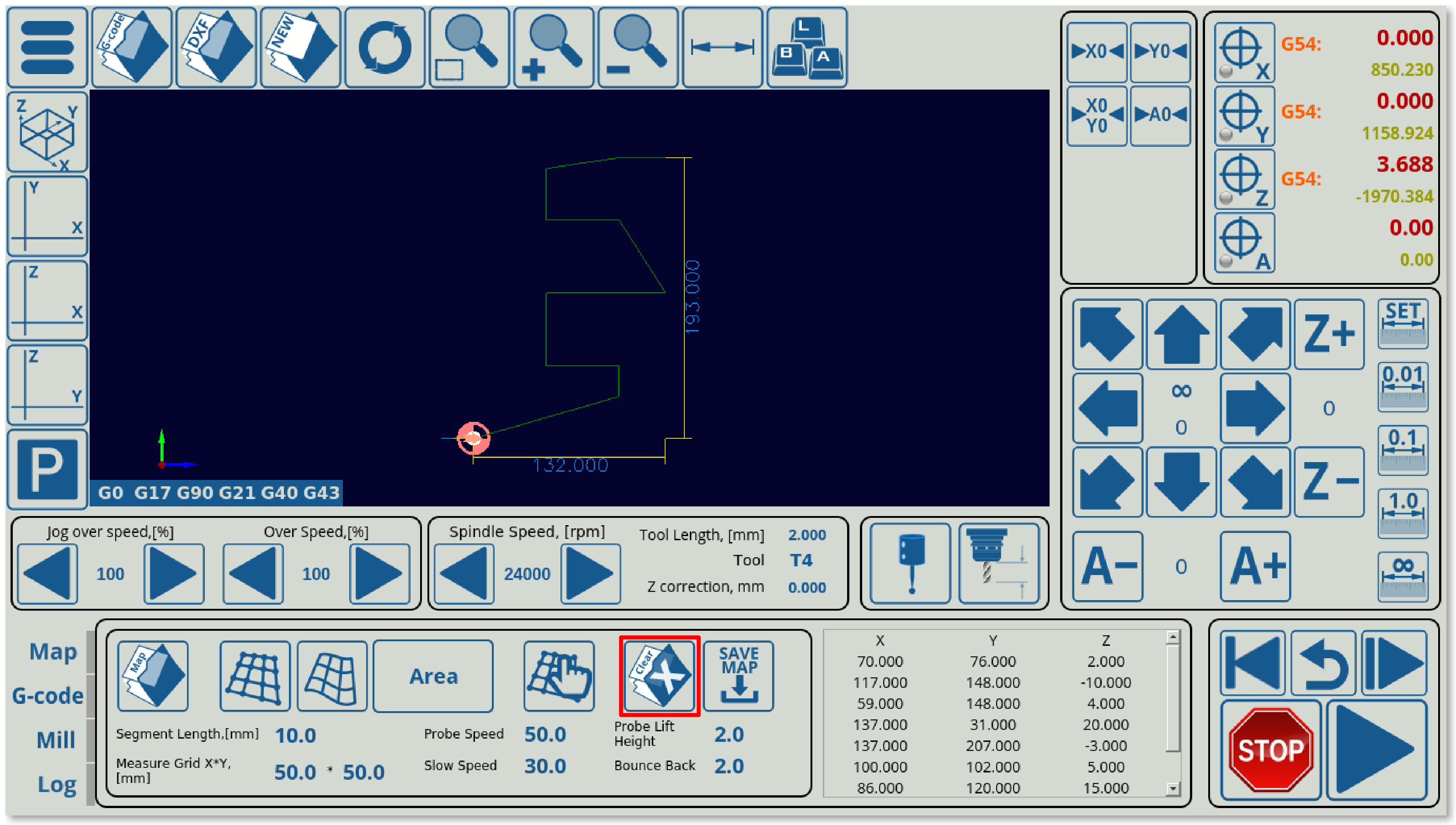
- If you would like to clear the existing generated map (for example, for the purposes of manually recording a set of points without data from the automatic measurements), you can do so using the Clear Map button.
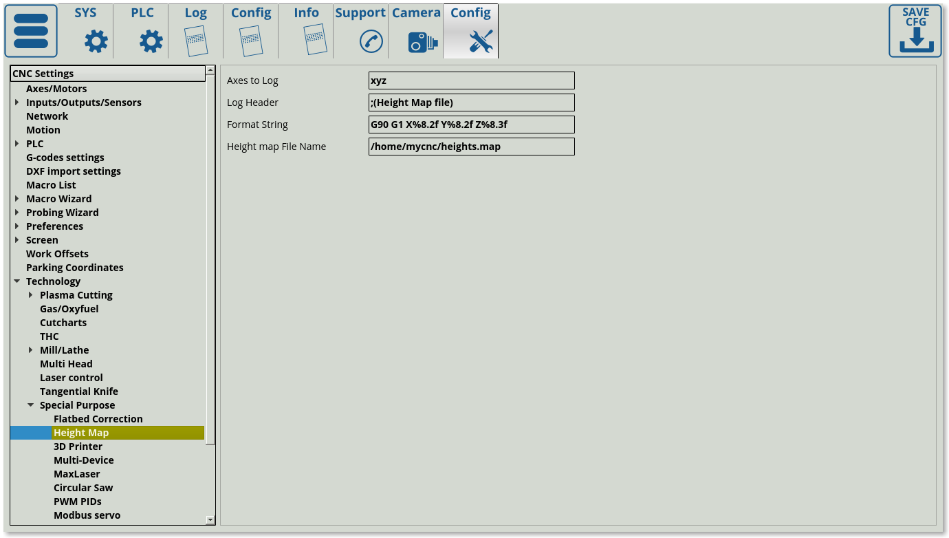
- If you would like to save the existing map in order to apply it to a G-code file at a later point, you can do so using the Save Map button. The map will be saved in the folder specified in
Settings > Config > Technology > Special Purpose > Height Map.
Setting up the probing procedure (beta users)
The 3D height map .xml file for the X1366M-series profiles is currently available on request (beta testing as of October 2019). In order to set up the profile once you have received the file, do the following:
- Head into home/.config/myCNC/profiles/X1366M (or X1366M4/M6 if using those) and switch the old x-bottab-left-mill.xml for the new provided file.
- Head into myCNC
Settings > Config > PLC > Hardware PLCand add theM180procedure if it is not already present.- On recent software versions, it can be added by going into
PLC > Hardware PLCTemplates, selectingM180(Double touch probing for Height Map) and clicking theSave PLCbutton in the lower right corner of the screen. After this, head back intoPLC > Hardware PLCand press theSave All,Build AllandSendbuttons to begin the PLC disk reflashing process. - On older software versions, add the M180 procedure by manually creating an
M180file in the Hardware PLC section and pasting the following code:
#include pins.h

do_probe()
{
  g0moveA(0,4,0-10000); //100 mm down
  timer=200; do{timer--;}while(timer>0);//wait till motion started
  do{
   code=gvarget(6060);
   if (code==0x4d)
    {
      gvarset(9121,1);
      timer=30;do{timer--;}while(timer>0);
      message=PLCCMD_MOTION_BREAK; timer=10;do{timer--;}while(timer>0);
      message=PLCCMD_MOTION_BREAK; timer=10;do{timer--;}while(timer>0);
      exit(99);
    };
  sens=portget(INPUT_PROBE);
  if (sens!=0)
    {
      code=1;
      message=PLCCMD_LINE_STOP;
      timer=10;do{timer--;}while(timer>0);
    };
  }while (code==0);
  do { code=gvarget(6060); }while(code!=0x4d);//wait till motion finished
};

do_rebound()
{
  //speed=gvarget(8254); //
  gvarset(7080,2000);       //
  timer=20;do{timer--;}while(timer>0);
  bounce=gvarget(8256);
  g0moveA(0,4,bounce);  //bounce
  timer=200; do{timer--;}while(timer>0);//wait till motion started
  do { code=gvarget(6060); }while(code!=0x4d);//wait till motion finished
};

do_lift()
{
  //speed=gvarget(8254); //
  gvarset(7080,2000);       //
  timer=20;do{timer--;}while(timer>0);

  lift_height=gvarget(8257);
  g0moveA(1,4,lift_height); //Lift Height
  timer=200; do{timer--;}while(timer>0);//wait till motion started
  do { code=gvarget(6060); }while(code!=0x4d);//wait till motion finished
};


main()
{
  message=PLCCMD_TRIGGER4_OFF;
  timer=2;do{timer--;}while(timer>0);

  sens=portget(INPUT_PROBE);
  if (sens!=0)
    {
      gvarset(7080,2000); //1000mm/min
      timer=20;do{timer--;}while(timer>0);
      do_rebound();
    };

  sens=portget(INPUT_PROBE);
  if (sens==0)
    {
      speed=gvarget(8253); //Probe Speed
      gvarset(7080,speed); //
      timer=20;do{timer--;}while(timer>0);
      do_probe();
    };

  do_rebound();

  sens=portget(INPUT_PROBE);
  if (sens==0)
    {
      speed=gvarget(8254); //Slow Speed
      gvarset(7080,speed); //
      timer=20;do{timer--;}while(timer>0);
      do_probe();
    };

   gvarset(5730,0);
   timer=20;do{timer--;}while(timer>0);

   do_lift();

   exit(99);
};
- Note that the probe sensor number is defined in the
INPUT_PROBEfield which is used in the M180 PLC procedure. This can be changed by going intoSettings > Config > PLC > Hardware PLC > pins.h, and switching the defaultINPUT_PROBEinput number to the one used by your particular setup. After assigning a new probe number, do not forget to once again press theSave All,Build AllandSendbuttons to reflash the disk.
Changelog
2019-10-15: Manual Height Probing and Clear Map buttons have been added. Manual Height Probing allows the user to take a height measurement in some arbitrary point on the working surface, while the Clear Map button allows to delete the current point array and start anew. Save and Open Map buttons should now be stable.
2019-10-07: Save and Open Map buttons are now operational (some stability issues might be present). The generated map point spread is now shown within the software.
2019-10-04: The Save and Open Map buttons do not work yet. These will allow the user to save the created map and to load a previous map to apply to the G-code file.

