Table of Contents
Pipe/Tube Cutting
Tube/pipe cutting is supported in myCNC (as of Nov 2025, round tubes and rectangular pipes are supported, with more geometries planned to be added soon).
The design of such pipes can be done within myCNC, via the CAD3D module. This CAD3D module is already built-in on supported profiles, or can be added to an existing profile via the action=“cad3d-open” line (see Screen Editing and Configuration for more information on editing the GUI of your existing profile).
CAD3D
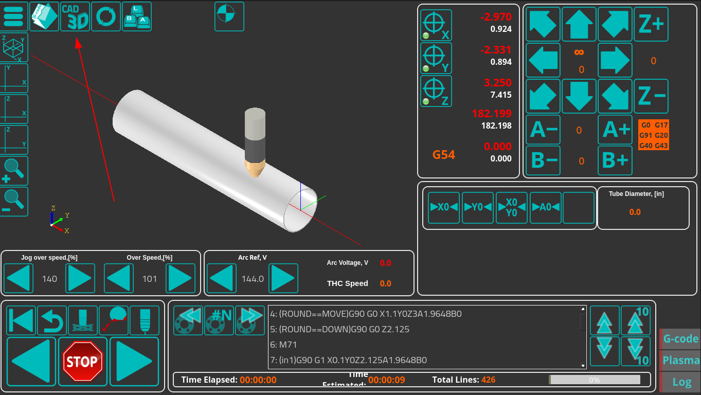
The CAD3D module is opened by pressing the CAD3D button on the main profile screen:
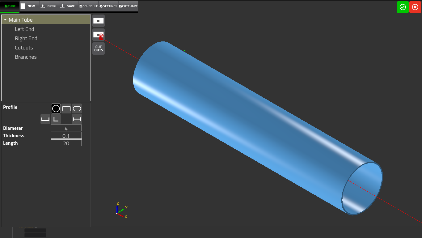
Upon opening the CAD3D module, the user is presented with the main design screen of the pipe/tube project. It consists of the following buttons and on-screen elements:
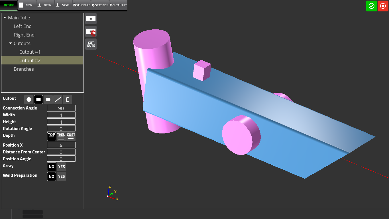
- Tube - allows the user to set the geometry of the tube (selecting end geometry, cutouts and branches)
- New - creates a new project
- Open - opens an existing pipe cutting project
- Save - saves the current project on your computer
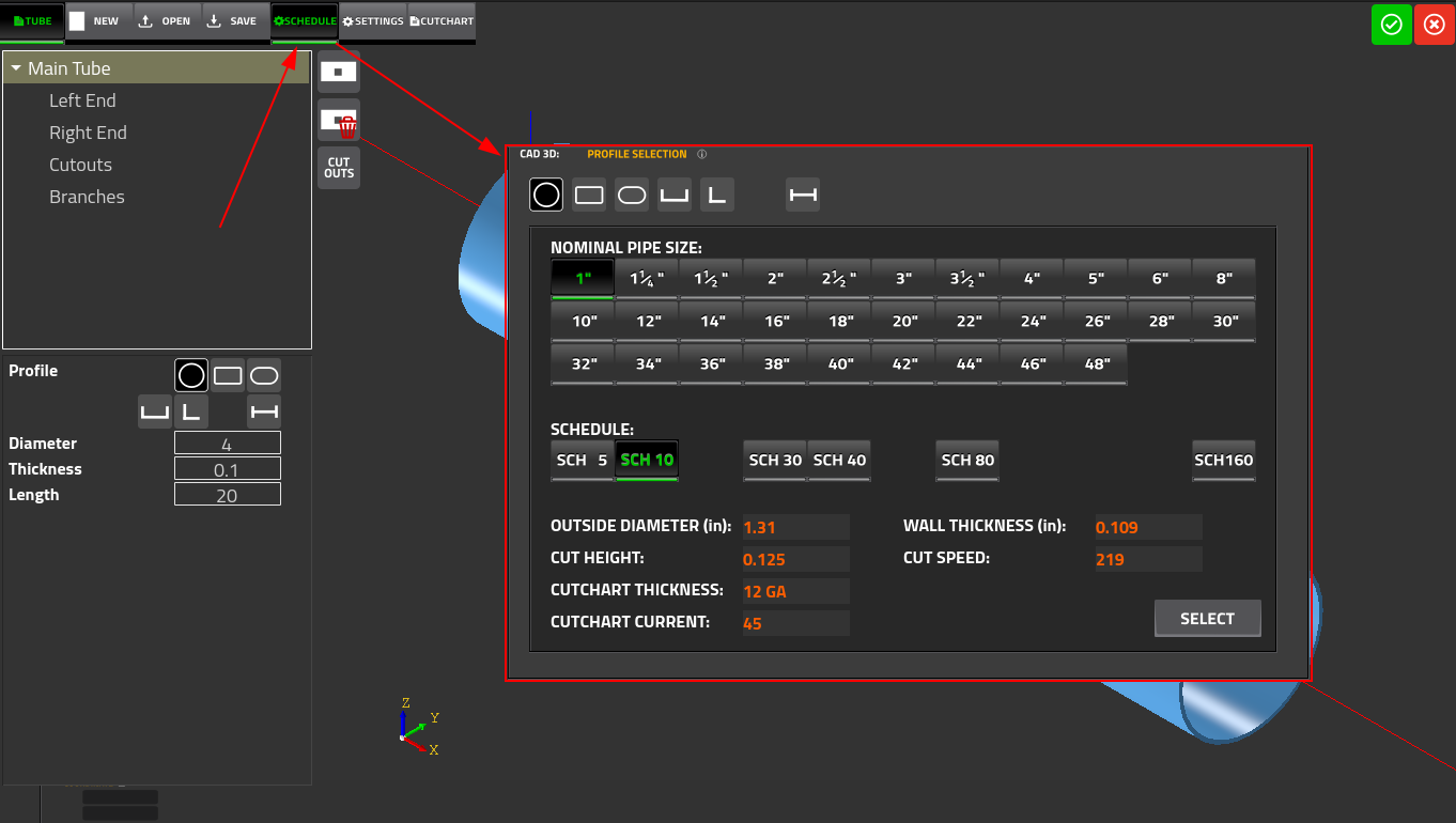
- Schedule - allows the user to pick from a variety of profiles, select the nominal pipe size, and select from a list of standard pipe schedules
- Settings - shows the loaded settings for currently selected plate, current, speed, cut height and kerf
- Cutchart - shows the currently loaded cutchart. These fields are often populated directly from the Schedule window.
In addition to those buttons on the top of the screen, the user is also presented with a visualization of the pipe.
The Schedule screen is show below:
This window allows the user to select the following:
- Material profile (as of Nov 2025, circular tube or rectangular pipe). Support for additional profiles is currently being developed.
- Nominal pipe size, ranging from 1“ diameter (1×1” rectangular profile) to 48“ diameter (10×10” rectangular).
- Schedule/wall thickness. The list of standard pipe schedules ranges from 5 to 160.
The Settings screen is shown below:
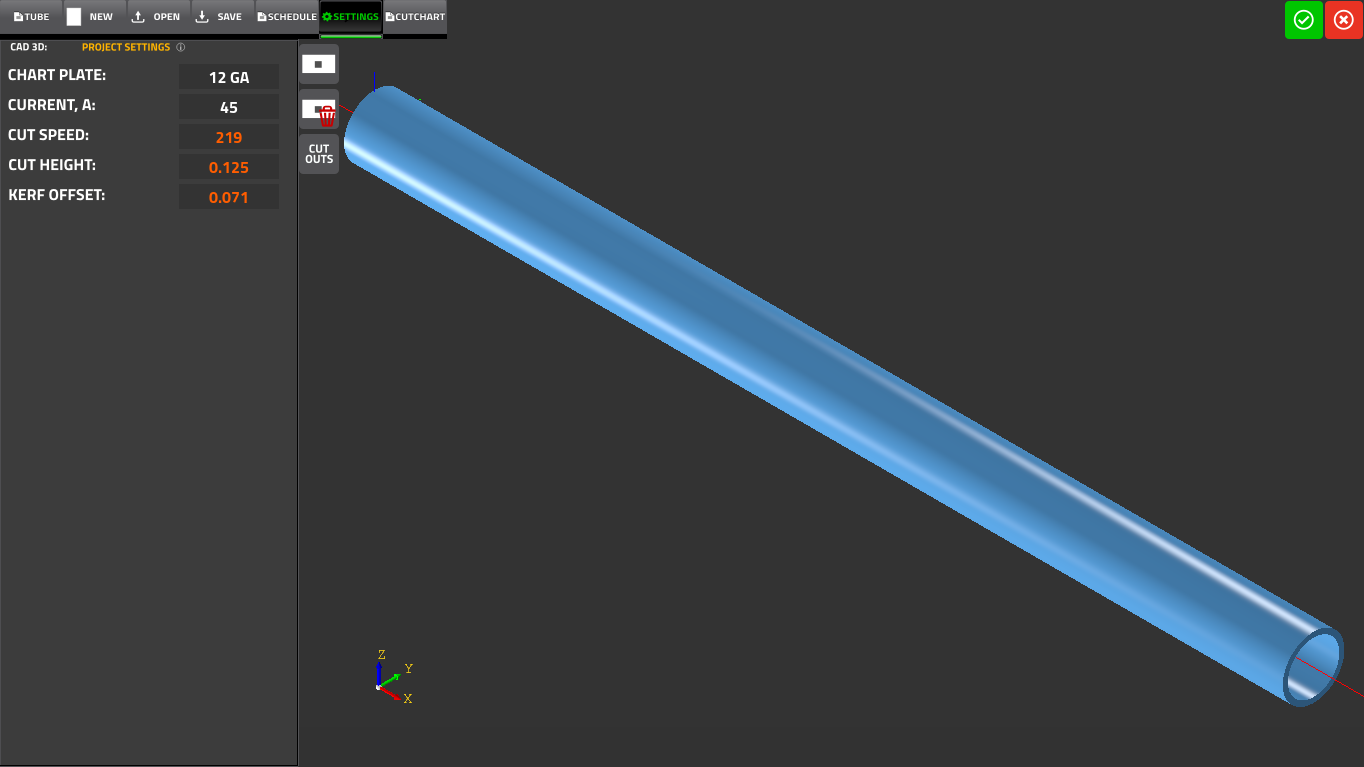 These settings are largely populated from the Schedule tab, and consist of the following:
- Currently loaded Chart Plate (for example, 3/16“)
- Current, A
- Cut Speed
- Cut Height
- Kerf Offset
The Cutchart screen is shown below:
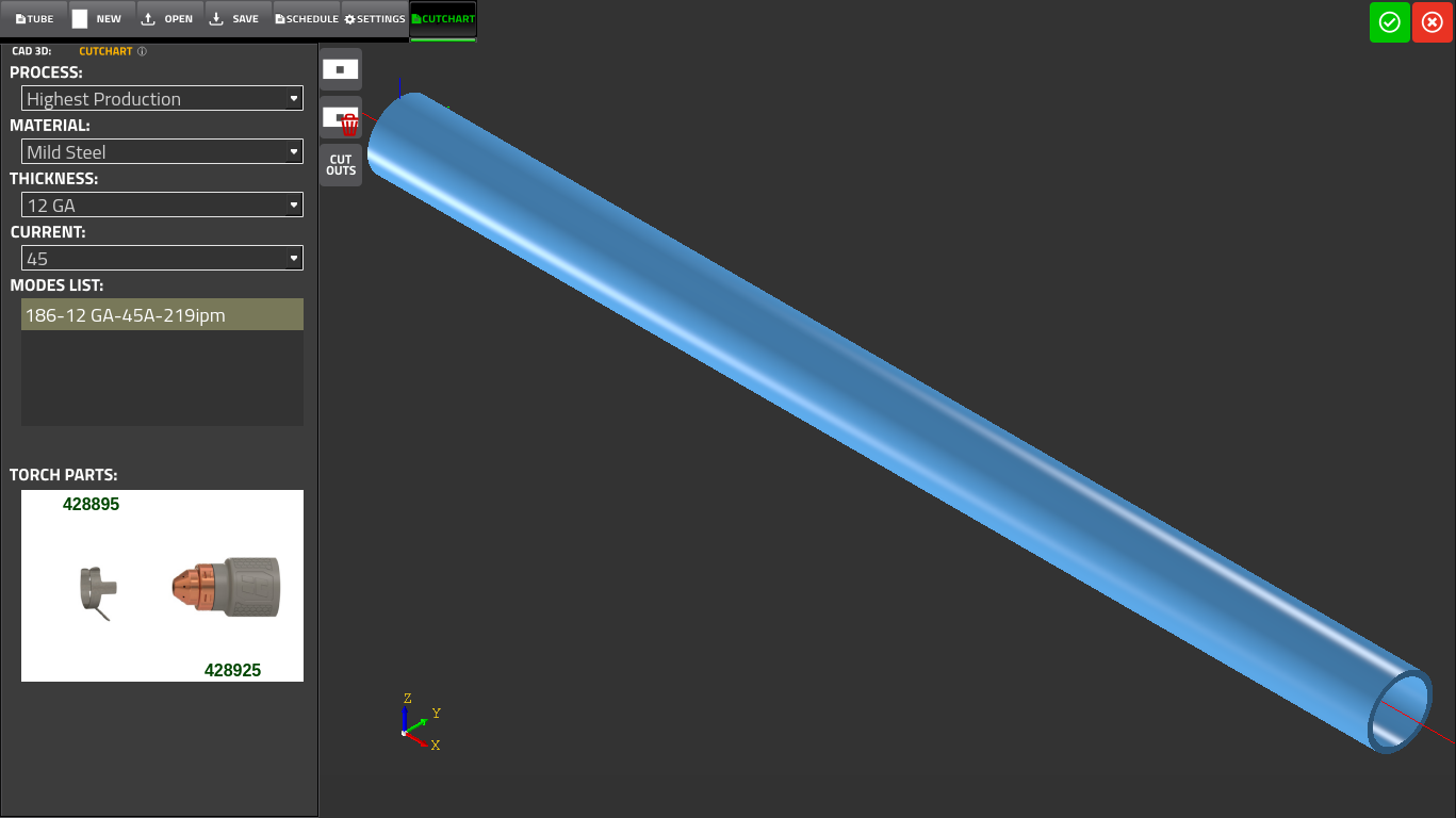
For more information on cut charts, please see the following manual: Cutcharts
The Tube tab allows the user to customize the project further, with different cutouts and pipe end geometries:
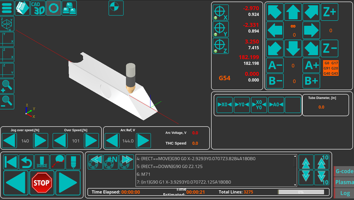
Once the design step has been completed, press the green button in the top right corner of the CAD3D module to generate the G-code file that will be brought over to the main screen of the myCNC software:
Configuration settings
The configuration settings are available in Config → Technology → Plasma Cutting → Tube Cutting.
The following settings are available:
- Tube Cutting mode: turns the tube cutting modes ON and OFF. Toggling between tube and sheet cutting is available on the main screen of the X1366PYT profile (top bar). The following modes are available (in addition to Disabled, which turns tube cutting off):
- X Tube
- Y Tube
- X Tube (Diameter - 2*Thickness)
- Y Tube (Diameter - 2*Thickness)
- Ratio1: Number of pulses per one full revolution (numerator coefficient). Stored in global variable #7451.
- Ratio2: Denominator coefficient, typically equal to pi (3.14159). Stored in global variable #7457.
- Y Tube Diameter: in mm, stored in global variable #7455
- Y Tube Thickness: stored in global variable #7456
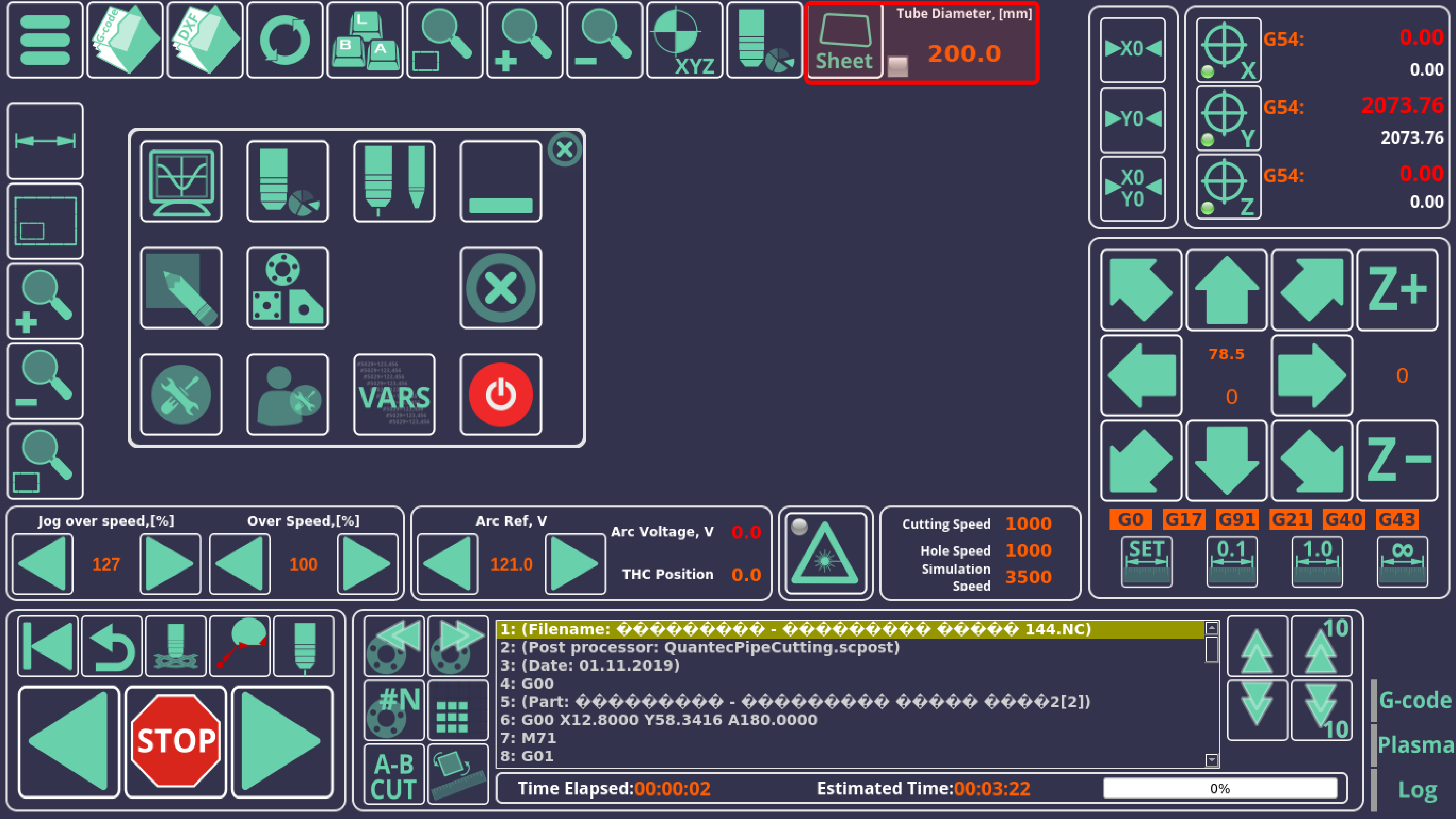
The options for switching between sheet and tube cutting can be shown on the main screen (for instance, in the example below in the X1366PYT profile). You can use the dedicated button, or switch via global variables (global variable #7453).
When cutting normally (for applications other then pipe cutting), the Y-axis pulse-per-unit value is taken from the default Axes/Motors field in the myCNC Settings (Settings > Config > Axes/Motors > Pulses per Unit).
In contrast, when switching to the “Y tube cutting” mode, this value is changed and calculated using your Ratio1/Ratio2 and pipe diameter.
Global variables reserved for pipe cutting
| Name | Global variable number | Description |
|---|---|---|
| GVAR_YTUBE_RATIO | 7451 | Ratio1 (pulses per revolution - see above) |
| GVAR_YTUBE_ORIGINAL | 7452 | |
| GVAR_YTUBE_CUTTING | 7453 | Specified the selected mode for tube cutting. See below for more info. |
| GVAR_YTUBE_DIAMETER | 7455 | Y Tube diameter |
| GVAR_YTUBE_THICKNESS | 7456 | Y Tube thickness |
| GVAR_YTUBE_RATIO2 | 7457 | Ratio2 (see above, normally equal to 3.14159) |
| GVAR_YTUBE_RESULT_RATIO | 7459 |
The #7453 global variable, which specifies the currently selected tube/pipe cutting mode, can have the following values:
- 0 - off
- 96 - X Tube
- 97 - Y Tube
- 98 - X Tube D-2*thickness
- 99 - Y Tube D-2*thickness
In cases where the #7453 variable is equal to 96-99, the pulse-per-unit value is recalculated so that the corresponding axis is operating in degrees. If the #7453 value is equal to 0, then the original PPU value is returned.
Pipe cutting demo
A video illustrating myCNC's pipe cutting capabilities is available here:
A CAD3D video demonstration with bevel cutting is available here:

