Table of Contents
Homing Procedure Setup
This article is designed to introduce the reader to the basics of the homing procedure using myCNC software. The homing procedure is done using sensors (optical, mechanical, etc) that are set up on the edges of the machine's working surface in order to find the initial machine position (the Home position). This setup can be done for every axis that your machine is using.
A quick video recap of the full manual is presented in this video:
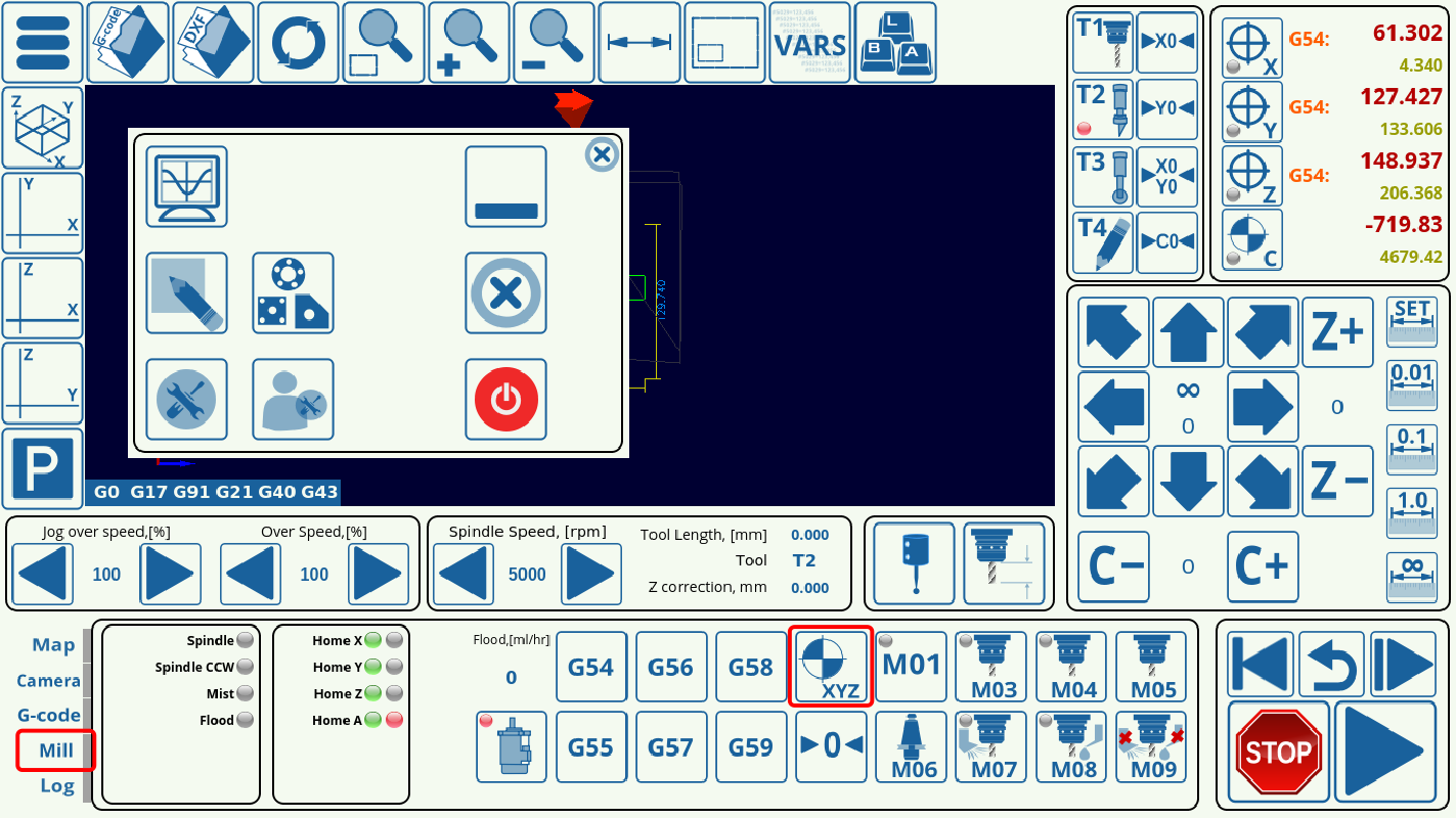
A lot of times, the homing procedure is initiated automatically upon program start, etc. To initiate the process manually, a Homing XYZ button is available in the Mill tab of the myCNC software (in X1366M, X1366M4, X1366M4E and X1366V profiles - available in the Plasma/Gas tabs in X1366P and X1366G profiles respectively):
In order to set up the homing procedure, do the following:
1. Go to CNC Settings > Config > Macro List > M138, and set up the homing procedure for the necessary axes by commenting out the axes and commands which are not required for your particular setup. This is done by adding ; in front of the commands, as shown in the screenshot below. For the configuration used in this example, the machine uses three axes (x, y and z), so the a-axis is not required, as well as the commands in the first half of the macro.
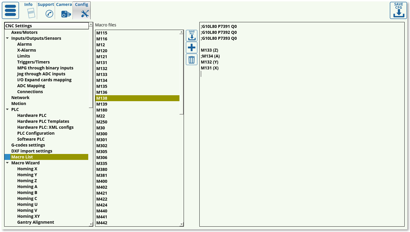
The code for a three-axes machine will therefore look like this:
;G10L80 P7391 Q0
;G10L80 P7392 Q0
;G10L80 P7393 Q0

M133 (Z)
;M134 (A)
M132 (Y)
M131 (X)
Note that the Z axis comes first, as the machine usually needs to lift the tool up before moving it in the xy-plane as to not crash into any obstacles.
A quick explanation of what each line of the above code represents:
- The first four lines (G10L80 P7391 Q0, etc) will simply set a zero for a variable that indicates the need for homing (variables #7391, etc). This will allow the user to simply forego the homing procedure by effectively indicating that the homing flag for each axis has been set to zero (so that no homing is needed).
- If the actual homing is required, the user needs to comment out the commands to set the flags to zero, and to run actual homing procedures (M133, M134, etc). Therefore, one or the other has to be commented out.
- The
;symbol commends out the line, anything in brackets such as (A) is also a comment
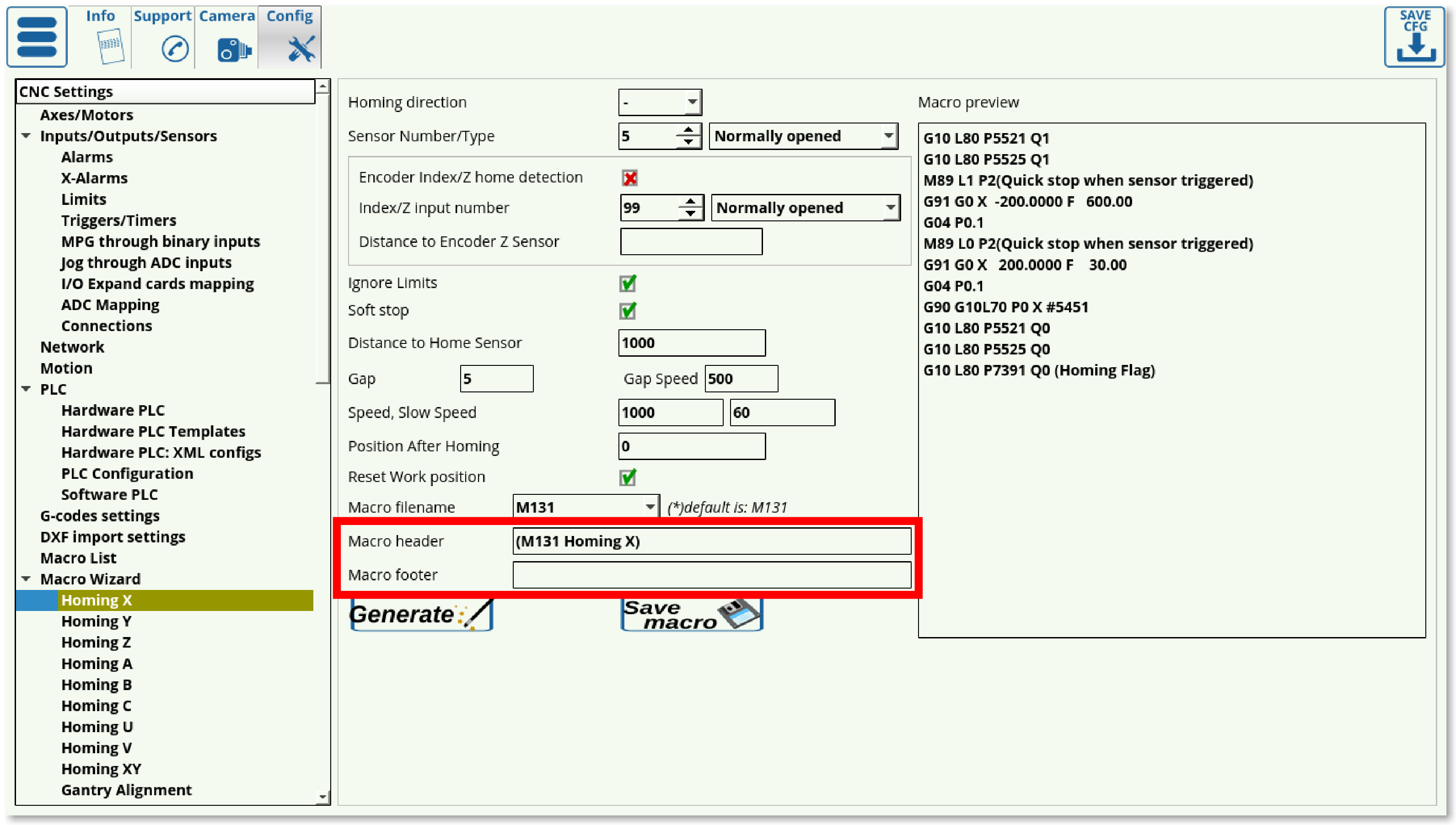
2. Open CNC Settings > Config > Macro Wizard and select the particular axis you would like to run the homing procedure for (Homing X in case of this example). The screen presented to you will look as follows:
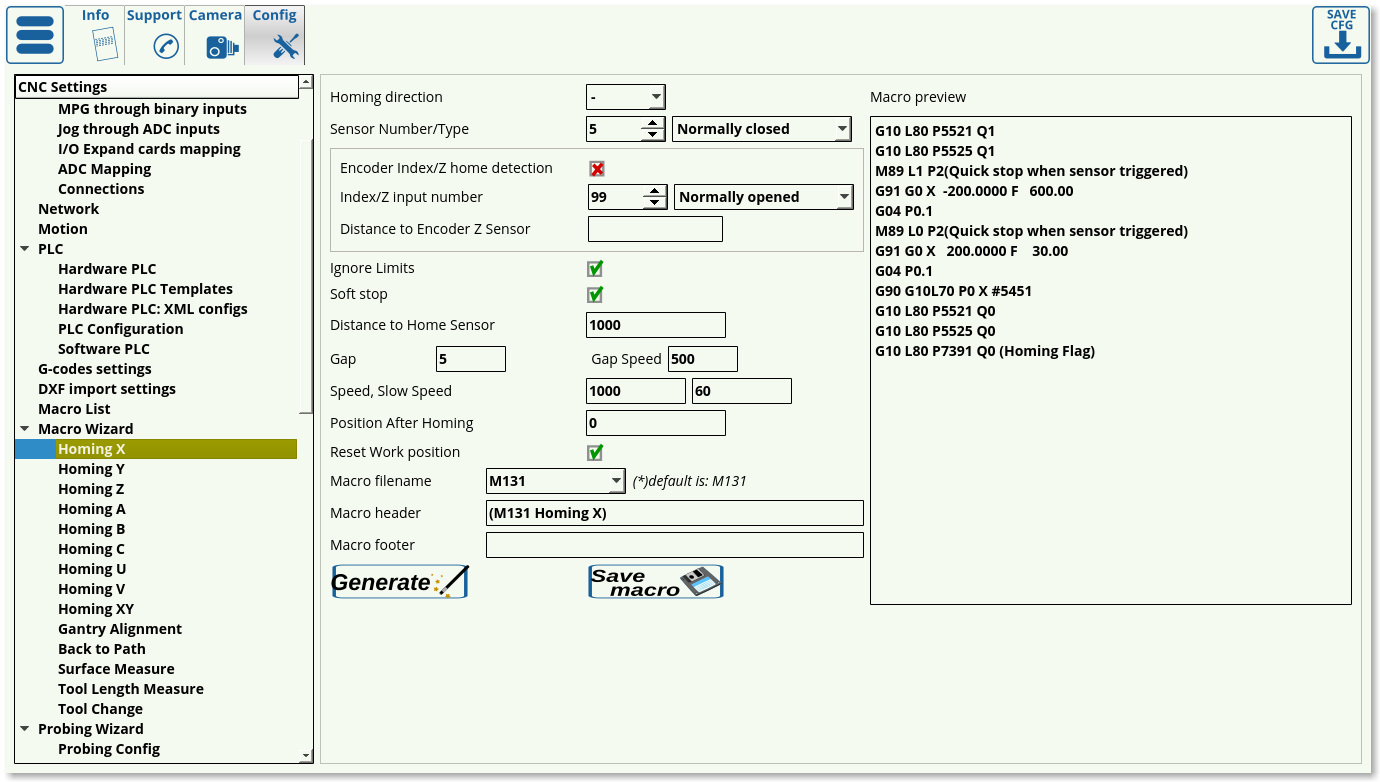
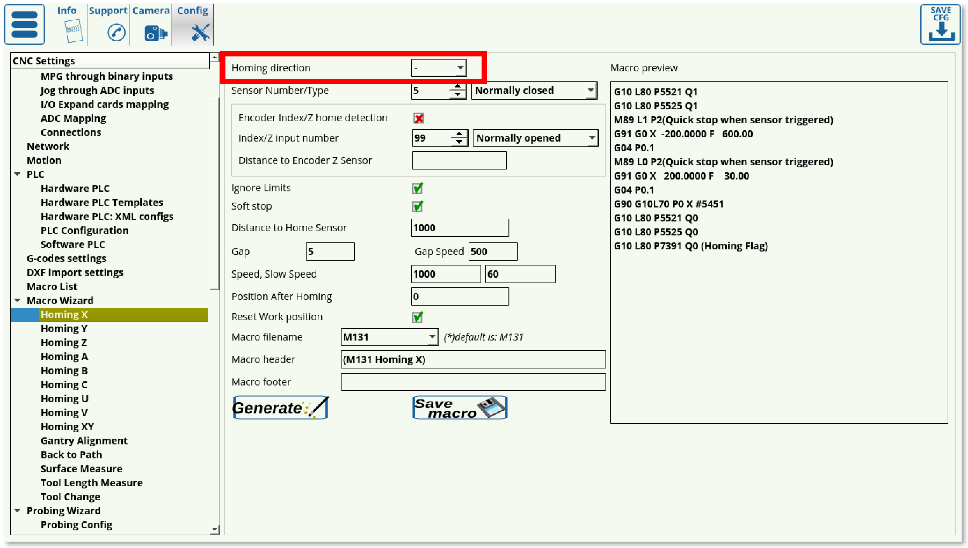
3. Select the Homing direction for the machine. This is selected depending on where your sensor is located in relation to the working bit of the machine. If the machine will have to move in the negative x, y or z direction to find it, select -. If the machine will have to move in the positive x, y or z direction, select +.
4. Select your sensor number (depending on the input number to which you have connected the sensor) and its type (normally opened or normally closed).
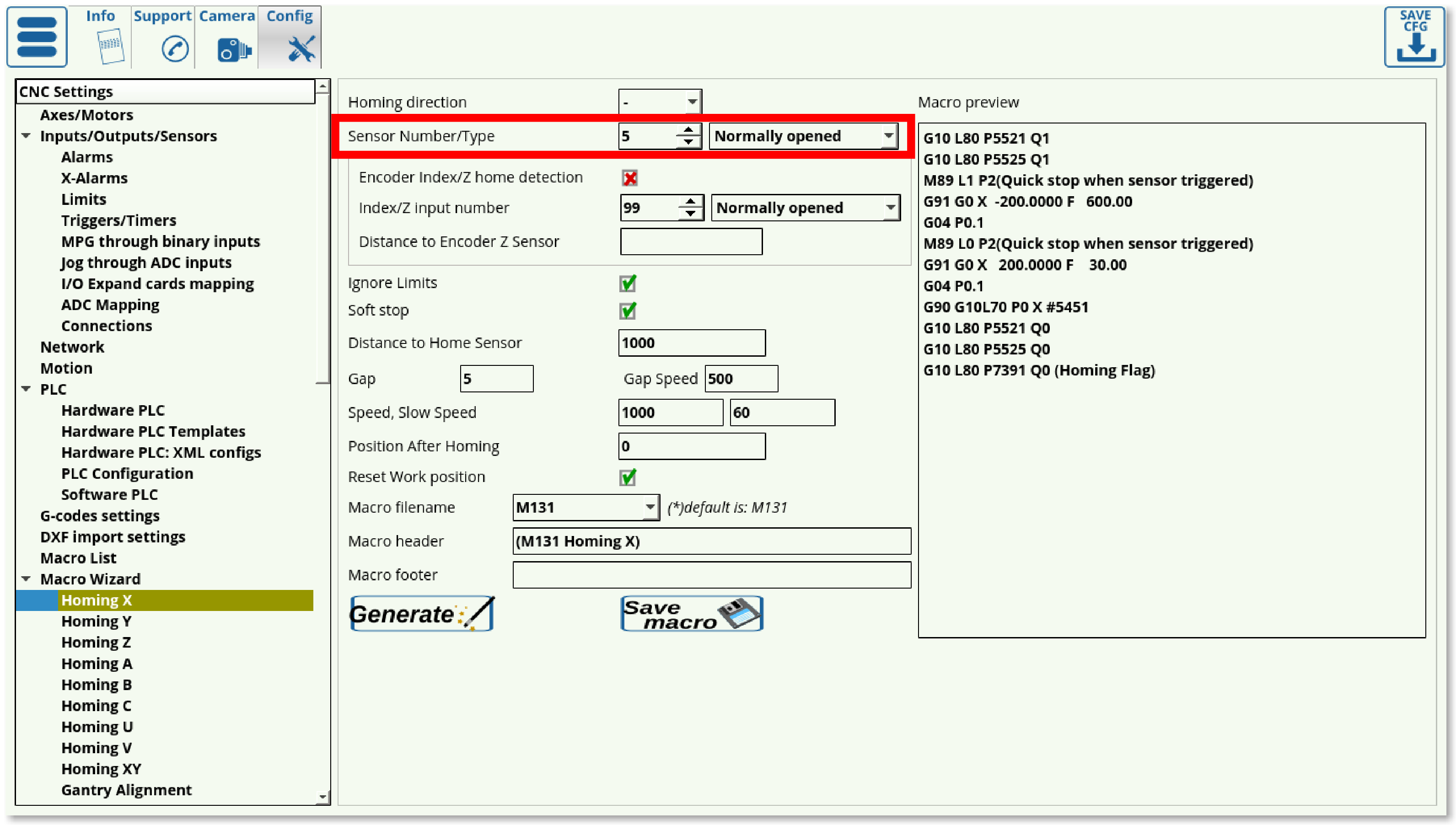
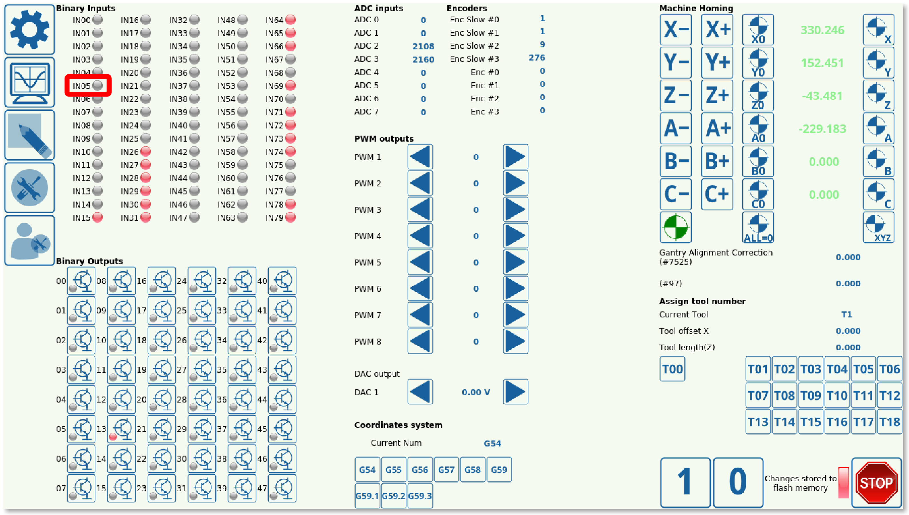
Note that the normally opened or normally closed does not depend on the particular sensor or sensor type you are using, but rather on the way it has been set up in myCNC software. In case of this example, Sensor 5 is used, with it being normally opened as can be seen in the System Diagnostics window:
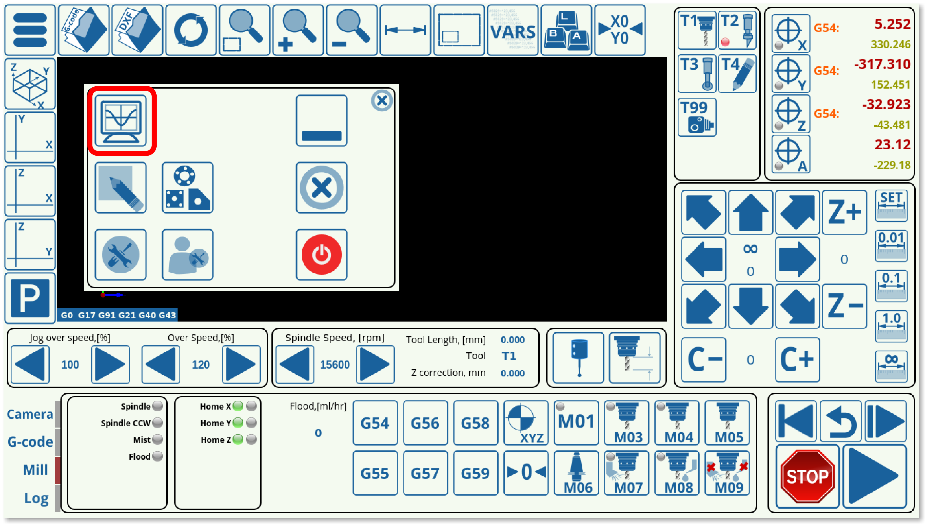
As can be seen from the System Diagnostics window, Sensor 5 is normally open as the indicator light is not on. However, that behaviour can be inverted in CNC Settings > Config > Hardware > Common Hardware Settings, so it is always recommended to check the System Diagnostics window to find out what the normal behaviour of the sensor has been set up as.
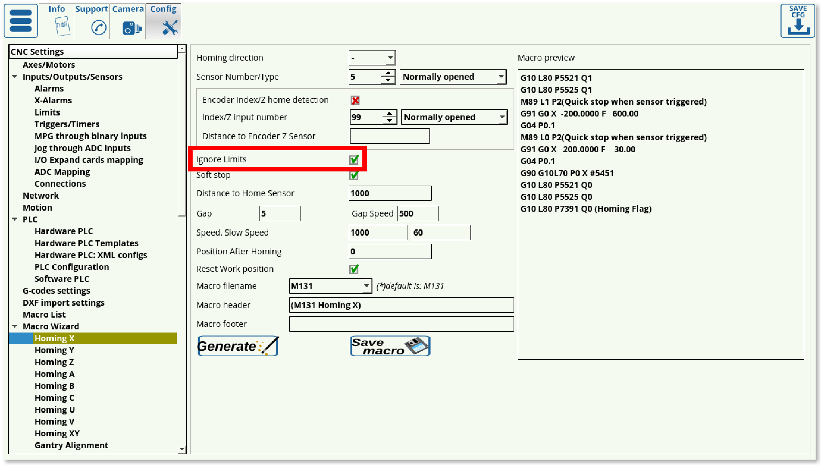
5. Choose your Limits behaviour in the Ignore Limits field. Set the check mark to ON if the sensor you are using for homing is the same as the one you are using for your limits (most common case), and set it to OFF if you are using multiple sensors.
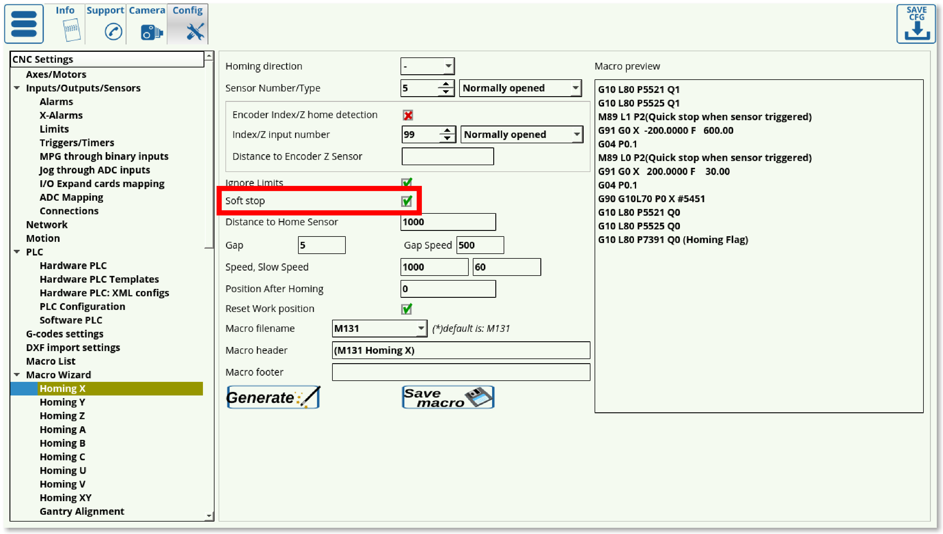
6. The Soft Stop setting allows for a gradual stop after the sensor has been passed (especially useful with optical sensors). It is highly beneficial to use the soft stop setting in order to not damage the machine moving at a high homing speed that's coming to an abrupt stop due to triggering the sensor.
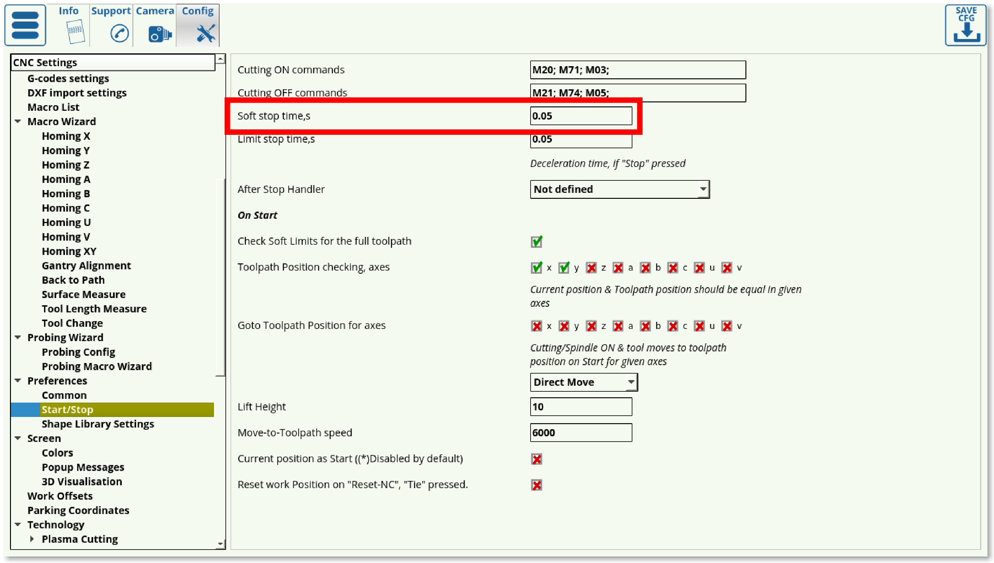
The Soft Stop time can be specified in CNC Settings > Config > Preferences > Start/Stop. Note that there must be some clearing after the sensor has been passed, as to allow for the Soft Stop to take place without crashing into an obstacle (such as a wall).
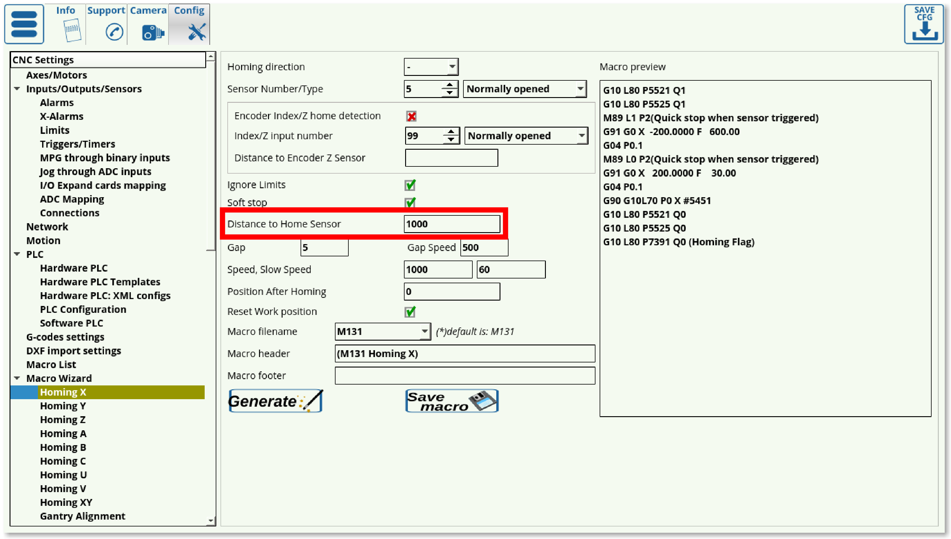
7. The Distance to Home Sensor should be set to be slightly higher than the maximum length that the working piece will have to travel to find the homing sensor. This depends on the particular size of your machine.
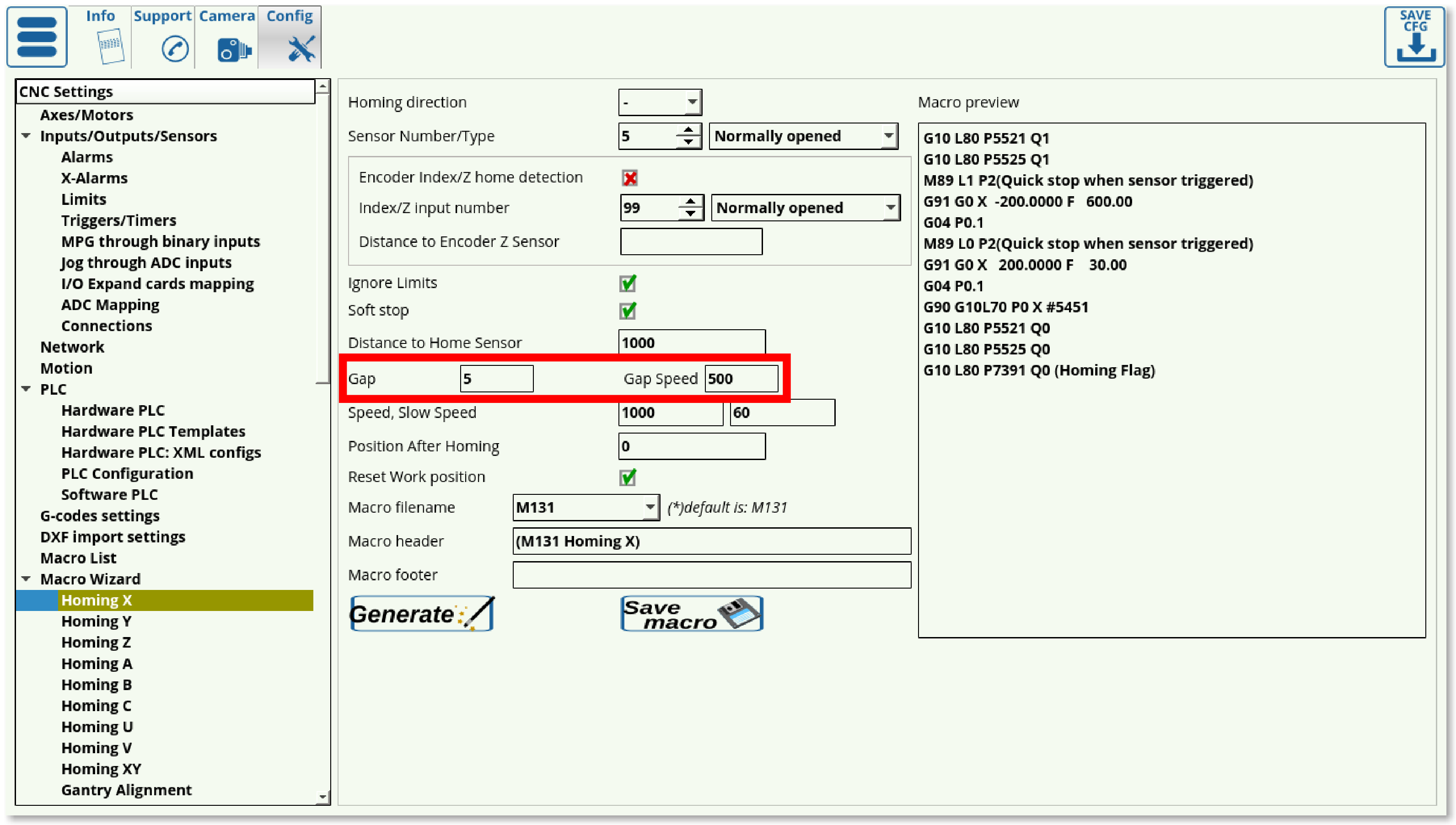
8. It is sometimes desirable to set the homing position to be slightly further away from the edge at which the sensor is located, so that the Home position is not right at the very edge of the working space. Using the Gap setting, the user can add a gap between the sensor position and the new software Home position (5 mm in case of this example). The Gap Speed will describe the speed with which the machine moves between the sensor (located at the edge) and the gap end (located closer to the centre):
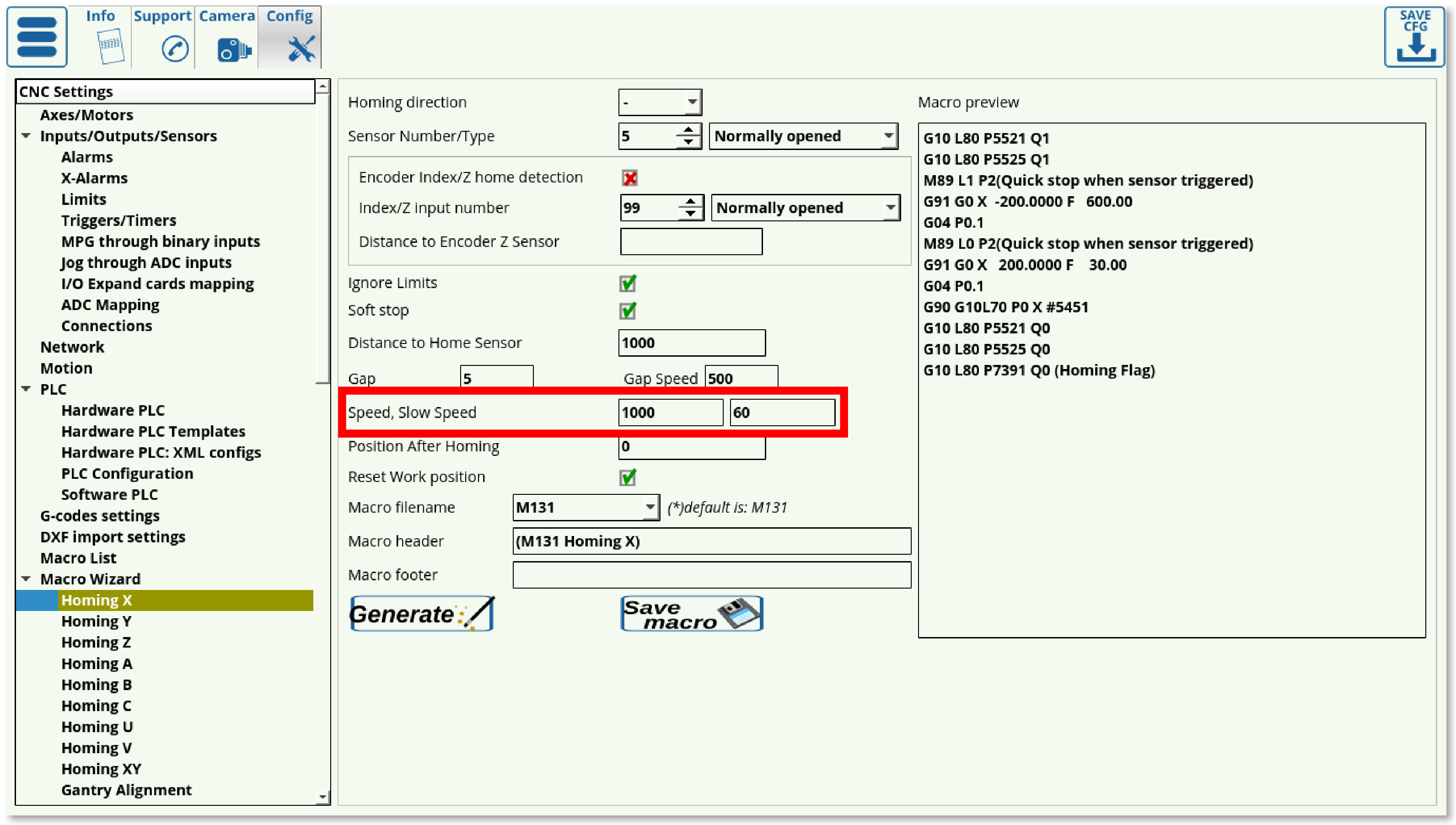
9. The Speed field specifies the speed at which the machine is moving during its initial movement towards the sensor. After the machine triggers the sensor, it starts to move back in order to find the precise spot at which the sensor has been triggered, at the Slow Speed.
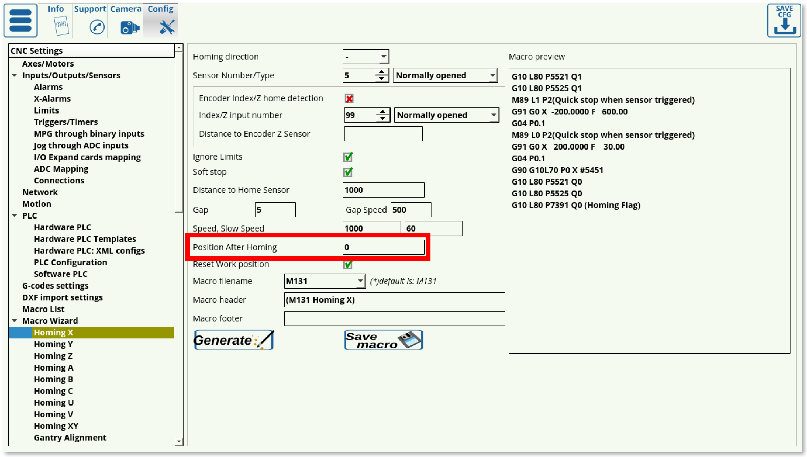
10. The Position After Homing field specifies the value assigned to the position after the homing. For example, if the homing for x-axis took place in the left corner of the workstation, then this x-position will be 0. If, however, the homing sensor was on the right, and the machine is 1000 mm wide, then the homing position will be specified to be 1000.
11. Choose whether you want to reset your Work Position or not after the homing is done.
12. Choose your Macro filename (it is recommended to keep the default macro filenames unless otherwise required). The default macro filenames are as follows:
- M131 for the Homing X procedure
- M132 for the Homing Y procedure
- M133 for the Homing Z procedure
- M138 for Homing XYZ
13. Add any necessary macros to the Macro Header and Macro Footer if so desired. These will be added in the beginning or in the end of the Homing procedure respectively. THESE FIELDS ARE USUALLY LEFT BLANK.
Any macro in brackets such as this:

(M131 Homing X)

is "commented out", disabling its addition to the Homing procedure.
Add the necessary macros without brackets, separated by a semicolon such as this:

M5;M9
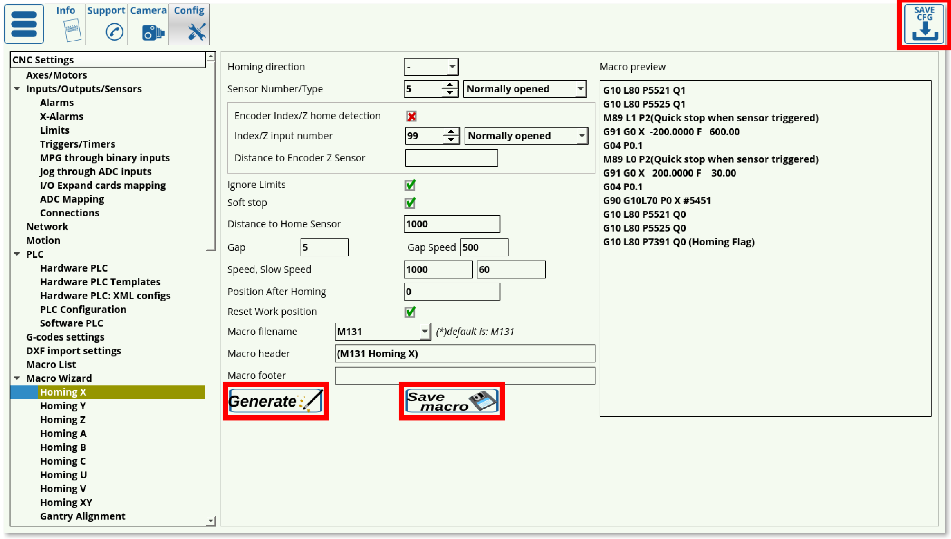
14. Press Save Configuration, then press Generate and Save macro.
Using Incremental Encoders
These settings allow for a higher accuracy during the homing procedure, however they require using an incremental encoder which might not always be feasible. These settings are located on the same screen, as shown below:

1. Set the checkmark to ON for the Encoder Index/Z Home Detection in order to use this setting.
2. As with the sensor from Step 4 of the regular procedure, set your sensor number and its normal behaviour.
3. Set the Distance to Encoder Z Sensor (usually used on Linear Encoders). This is useful when a linear encoder is located some distance away from the sensor, and is set to be slightly smaller (on the scale of nearly a millimeter) than the actual distance to the encoder. This setting is not necessary, however it does allow the user to lower the required time that the machine spends on the Encoder Z Home Detection.
Checking sensor contact at homing start
In certain situations, homing may start while the homing sensor is already “engaged” (i.e. the sensor is in a state that indicates that contact has been made already). This may be due to a faulty sensor/setup, or it may be due to the fact that the sensor is touching the machine. In that case, it is not desireable to continue moving the sensor any further, as this may physically break it.
To prevent this, a Hardware PLC can be used. An example of such a PLC is M286, which is generated automatically for tasks such as Surface Measure. For the Surface Measure procedure, the macro code that includes M286 will look the following way:
M286 P[35] L[256+2] (lift up sensor activated, sensor normally opened)
or
M286 P[256+35] L[256+2] (lift up sensor activated, sensor normally closed)
Note that the 35 part of the code refers to port 35 - this value must be customized depending on the input port used.
The code for M286 Hardware PLC itself is shown below:
////// FILE GENERATED AUTOMATICALLY. DO NOT EDIT IT. //////
#define input  var00
#define state  var01

main()
{

  input=eparam & 0xFF;	         //P-parameter lo byte
  state=(eparam>>8) & 0xff;    //P-parameter high byte
  axis=  (eparam>>16) & 0xff;  //L-parameter lo byte
  dir=    (eparam>>24) & 0xff;  //L-parameter high byte

  axis_mask=0;
  if (axis<6) {axis_mask=1<<axis;}
  else { exit(99); };

  length=100;  //1mm
  if (dir==0) {  length=0-length;  };

  gvarset(7080,1000);  //set speed

  do {
  a=portget(input);
  if (state==0) {   if (a==0)  { exit(99); };  };
  if (state!=0)  {   if (a!=0)   { exit(99); };  };

  g0moveA(0, axis_mask, length);	      //incremental programming;
  timer=200; do{timer--;} while (timer>0);  //wait motion started
  //wait motion stopped
  do { code=gvarget(6060);  } while (code!=0x4d);
  }while (1);

  exit(99);
};
This PLC will check if the input port is “triggered”, and will move the machine in 1mm increments until the the conditions are met.
If the port is in its “correct” state, the PLC will exit immediately.

