Table of Contents
Dental Aligners in myCNC
Relevant articles:
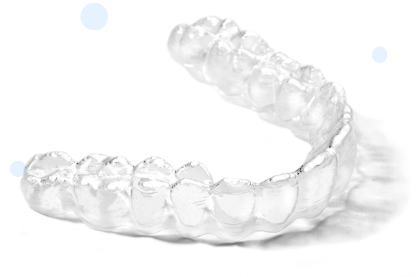
The myCNC software features a cutting mode that allows generating cutting programs with a focus on dental aligner manufacturing. In this mode, given an array of XYZ points, myCNC can generate a program that takes into account the rotary axis and the orientation of the workpiece (orienting the work part to be normal to the trajectory of the cut).
Variables
The following variables are used in myCNC for this application:
| Variable name | Variable number | Description |
|---|---|---|
| GVAR_ALIGNER_MODE | 5810 | Enable Aligner Cut generation - turn on contour generation based on an array of XYZ coordinate points |
| GVAR_ALIGNER_ANGLEA | 5811 | Inclider angle (A) |
| GVAR_ALIGNER_OFFSETZ | 5812 | Z-axis offset for Cutting Depth Correction |
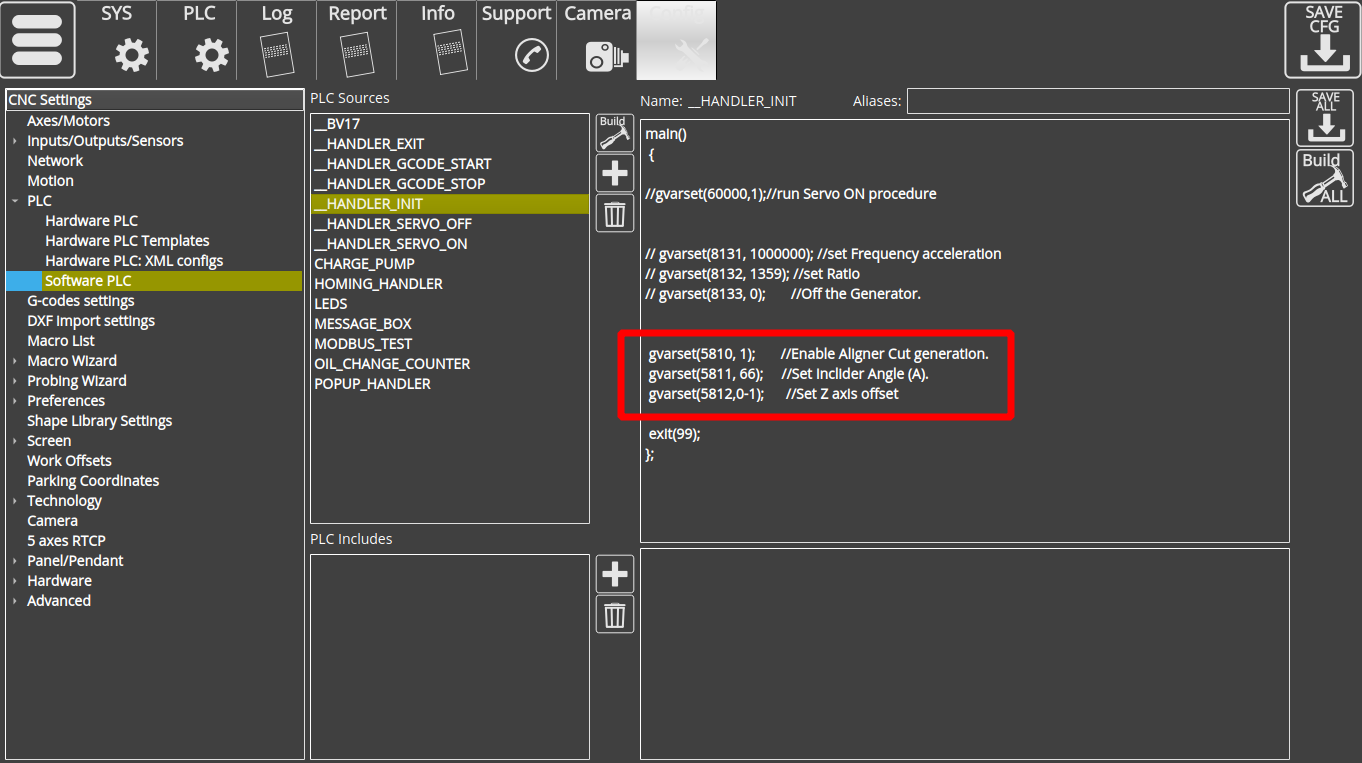
These variables can be interacted with either via Software PLC (as in the example below, via HANDLER_INIT), or via on-screen GUI elements that will be discussed in more depth later:
The following code is relevant to the topic of discussion:
gvarset(5810, 1);       //Enable Aligner Cut generation.
gvarset(5811, 66);     //Set Inclider Angle (A).
gvarset(5812,0-1);      //Set Z axis offset
If the global variable #5810 is enabled (set to 1), then the myCNC system expects an array of XYZ points in the loaded file, which it automatically converts to G-code upon import.
Note the way the negative Z-axis offset is inputted - due to the way negative values are calculated, it is necessary to type it out at 0-1 rather than simply -1.
The HANDLER_INIT functionality (a Software PLC that launches whenever the myCNC application is opened) is examined in more detail in the following video:
GUI
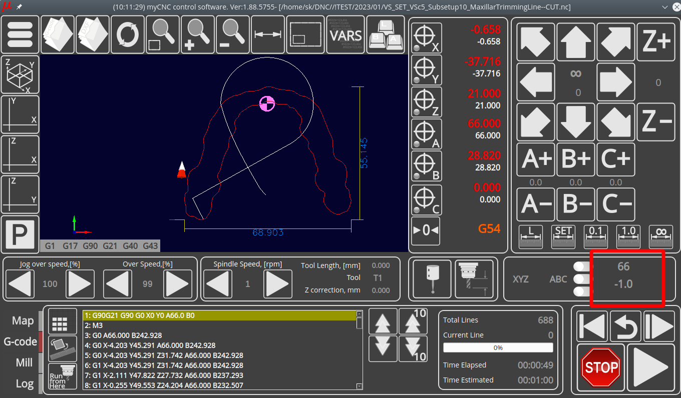
It is also possible to add on-screen GUI elements that will display this information, such as in the screenshot below:
In the screenshot, the first number represents the incliner angle, while the second represents the Z-axis offset. The following XML code is used:
<gitem where="x-3d" position="200;5" width="80" height="30"
 fgColor="##f-display" format="%d" fontSize="21"
 type="bdisplay" action="item:cnc-gvariable-5811"
 name="display-cnc-gvariable-5811"
 bgColor="##b-display" displayWidth="80" fontStyle="bold">
</gitem>

<gitem where="x-3d" position="200;40" width="80" height="30"
 fgColor="##f-display" format="%1.1f" fontSize="21"
 type="bdisplay" action="item:cnc-gvariable-5812" name="display-cnc-gvariable-5812"
 bgColor="##b-display" displayWidth="80" fontStyle="bold">
</gitem>
An article on editing your profile screen to include a code such as the one shown in the example above is available here: Screen Editing and Configuration
Files
The files that are loaded into myCNC are expected to have a .txt extension. On output, a –CUT.nc label is added to the file name.
A section of an example file that may be loaded into myCNC using this method:
-26.353647 -47.955063 10.070404

-26.086842 -47.879990 10.351146

-25.795347 -47.787163 10.611996

-25.510485 -47.663895 10.861265

-25.263590 -47.497482 11.107270

-25.063272 -47.262436 11.374028

-24.902113 -46.978760 11.640160

-24.749945 -46.668941 11.888394

-24.576611 -46.355492 12.101460
This file, when loaded into myCNC, will be transformed and will have the following section in the beginning:
G90G21 G90 G0 X0 Y0 A55.0 B0
M3
G0 A55.000 B242.928
G0 X-10.183 Y45.291 A55.000 B242.928
G0 X-10.183 Y45.291 Z30.356 A55.000 B242.928
G1 X-10.183 Y45.291 Z30.356 A55.000 B242.928
G1 X-7.363 Y47.822 Z26.819 A55.000 B237.293
G1 X-4.868 Y49.553 Z23.711 A55.000 B232.507
If the first file was named, for instance, test1.txt, then the output will then be named test1–CUT.nc and will be stored in the same folder as the original.


