Table of Contents
FAQ (Unfolded)
Original page version: Frequently Asked Questions
General
Is a PC required to use the myCNC controller?
Yes, a PC is required to run the myCNC software, which will be used to control your myCNC board. You can use a full industrial PC (such as the one provided in some controller kits in our Shop), or you can use a small single board computer, such as a Raspberry Pi, an Odroid or a TinkerBoard. The links to download the myCNC software are available at our Downloads page.
Is a myCNC controller required to use the myCNC software?
Yes, a myCNC controller is needed to use most of the functions of the myCNC software. The main software itself is free and can be downloaded from our Downloads page. Please note that certain specialized software add-ons (such as G-code correction via DXF import with markers) are available as separate licenses which do have to be purchased in addition to the controller.
The software can be downloaded and tested in Simulation mode, designed to help the user get a feel for the software layout and functions. However, the Simulation mode is highly restrictive, with most features not accessible without a myCNC controller.
Can the myCNC software be customized to the client's specific needs?
Yes, the software can be extensively customized, both visually and under-the-hood (via custom PLC/macro commands). Client logos can be added to the main software screen, and the screens themselves can be customized via the XML configuration files which are open and available to every user. Read more about XML file editing here: Screen Editing and Configuration
The myCNC team also undertakes customization projects. The exact price depends on the size of the customization project and the necessary features. For more information, please contact us at sale@pv-automation.com.
What sort of technical support is provided?
The myCNC team provides technical support for our controllers and the CNC systems utilizing them. Our technical support can be broadly separated into two categories:
1) Free technical support
Free technical support includes things that are largely development-free, for example answering general setup questions such as:
- How do I set up the network settings?
- How do I use the probe sensor window?
It also deals with solving general user errors and issues which do not include a large amount of programming, such as:
- Help in finding errors within your G-code program
- Troubleshooting tips
- General recommendations for the selection of drives, sensors, etc (provided the team has experience with the particular configuration you are trying to implement)
2) Paid technical support
Paid technical support deals with more complex tasks for which it is difficult to give a standard generalized answer, and may include a large amount of programming on the part of the myCNC team. This will often involve the myCNC team remotely connecting to your computer/machine to work directly with your hardware.
Paid technical support typically covers things such as:
- Developing custom PLC procedures that have not been previously implemented in myCNC, or finding and identifying errors in your custom PLC procedures
- Step-by-step guidance on setting up the machine from scratch (includes a remote connection to your workstation).
- Help with creation of custom profiles and profile screens
The myCNC-ET7 controller comes with one hour of paid technical support bundled with your purchase. The myCNC-ET10 comes bundled with two hours of paid technical support.
For requesting technical support, or for more information on pricing, please use the Contact Us page form on our main website, or email us at mail@pv-automation.com.
Software Setup
What are the login credentials for a computer running a custom Linux build?
The login credentials for all Linux computers using the myCNC Ubuntu MATE installation are the following:
Login: mycnc
Password: operator
How do I navigate the myCNC software?
A short introduction to myCNC software is available here:
If you would like more information about all the particular buttons and on-screen elements in a particular myCNC profile, please consult the MyCNC Screen manual.
How to load G-code or DXF files into the software?
The files that you are attempting to load must be located in folders that are specified in the Settings > Config > Preferences > Common fields for NC code folders. If a folder that you would like to load your files from is missing, add it on a new line and press the Save Configuration button:

If a folder is not listed in the NC code folders list (or is not within one of the folders listed), you will not be able to open files from it within the myCNC application.
The following standard folders are used on Linux (Ubuntu MATE) installations:
~/DNC/
~/Desktop/G-codes/
To load file from your USB drive, you can add the following folder to the NC code folders list:
/media/
The ~ symbol allows you to not write out the whole /home/USERNAME/DNC line, however the full filepath can also be used.
The following standard folders are used on Windows installations:
C:\DNC
C:\DNC\LIBS
After you have listed the folders that you would like to have access to, you can open files using the Open G-code and Open DXF buttons from the main software screen:

How to update the software?
The procedure to update the myCNC application is described in detail in the following manual: How to update MyCNC Software
Here is a short video going through the steps to update the application:
How to update the profile?
There are a couple ways to update a profile which are described in the following manual: Update MyCNC Profile
Profiles are typically updated to obtain new PLC procedures, macros, and visual enhancements. Profile updates and software updates are separate actions.
It is not recommend to select to update the Variables, if updating the profile through the myCNC application, or to overwrite the cnc-variables.xml file inside your profile folder if performing a manual update. The variables file contains user settings which would be reset to a default state should a user overwrite this file - that is only recommended if a reset is necessary during the initial setup process.
If updating manually, many users also prefer to keep their PLC folder intact to make sure any changes unique to their setups do not get overwritten by the default configuration.
How to switch the profile / technology?
In order to switch the current technology / profile within the software (for example, to switch from the Mill profile to a Plasma profile, or from a Plasma profile to Tangential Cutting):
- Go into Settings > Info
- In the right panel, select the profile you'd like to switch to (for example, X1366P)
- Click the Save Profile button
- Reload the application

The myCNC software should now switch to the chosen technology profile.
Why do the changes to Config/Settings not take effect as soon as the Save Cfg button is pressed?
The settings in the Config panel are typically edited by the system integrator only when setting up the machine. After completing the setup process, or in cases when the settings within the Config tab are changed, it is recommended to restart the program. All changes to the settings available to the operator (from the main screen / via User Settings) take effect immediately without rebooting.
How to roll back to a previous version of the software?
The rollback process is sometimes necessary to test things on an older software version, or in cases where you would like to go back to the stable myCNC version from our test release. This process is described in the following Troubleshoot manual: Rollback to a previous version of myCNC software
How to restore a profile?
A video on this page goes through the steps to restore a profile in case you want to roll back to it: How to restore profiles
Note that restoring a profile and restoring the myCNC application are two different processes. The profile contains your individual program settings, as well as any visual changes that you might have done to the myCNC application, as opposed to the myCNC program itself which will contain key functionality and features.
How to set up homing?
The following video is available to aid the user with the homing procedure setup.
A full manual is available here: Homing Procedure Setup
How to remove the homing dialog that keeps popping up when starting the program?
The homing dialog is done through the HOMING_HANDLER Software PLC. If you would like to disable it, add a line saying exit(99); near the start of the code like so:

This will force the handler to exit before showing the popup. In order to bring the popup up again, simply delete the exit(99); line, or put two forward slashes in front of it, like so:
//exit(99);
For more information on this homing dialog, please consult the full Homing manual.
How to set up default I/O ports' names?
The default names for the I/O ports that can later be used in your Hardware and Software PLCs can be set up in the pins.h file (located by heading into Settings → Config → PLC → Hardware PLC → pins.h). A video on the pins.h file is available here:
How to change Screen Size and Position
- Open Settings Tab
- Open the Config Tab
- Select Preferences, Screen tab

There are few settings to control GUI screen size, position and window attributes
- Full screen - switch myCNC main window to full-screen mode (without Window title and borders)
- Maximize screen - switch myCNC window to Desktop Size but keep windows title and border
- Fixed screen size - set size in pixels for myCNC main screen window
- Fixed screen position - move a left-top point of the myCNC main window to the given position
It's supposed this setting should work the same way for all OS and Window Managers like
Windows 7/8/10, Linux KDE, XFCE or Mate Window manager. Unfortunately, window behaviour
DOES depend on OS/Window Manager. You might need to play with these settings to find a view
suitable for your needs.
How to change the Interface Language?
Open Settings Tab

Open the Config Tab

Select the Preferences > Screen tab

Change the Language two-letters language code, and press the SAVE button
Restart myCNC Software

How to change the program units (mm and inches)?
A quick video on switching mm to inches is available:
To change the system from one set of units to another, confirm the following options:
- Specify G20/G21 within the system (if that command is not already present in the G-code program). This can be done by typing the G20/G21 command (depending on the desired unit system) into the MDI. See video above for more information.
- Change the G-code settings (Settings > Config > G-codes settings > Linear Unit) to inch/mm.
- Change the Visualization settings (Settings > Config > Screen > Display Linear Axes In) to inch/mm.
Do not forget to save after steps 2 and 3.
How to check what a button/on-screen element does?
NOTE: This is an experimental feature, so not all functions might work as expected. It is not recommended to press the Save button in experimental “Edit XML config item” window under any circumstances.
For example, we might want to check how the parking buttons work.

- Goto Config – Advanced – UI Settings
Enable Allow to edit cnc-screen.xml checkbox, Press “Save” button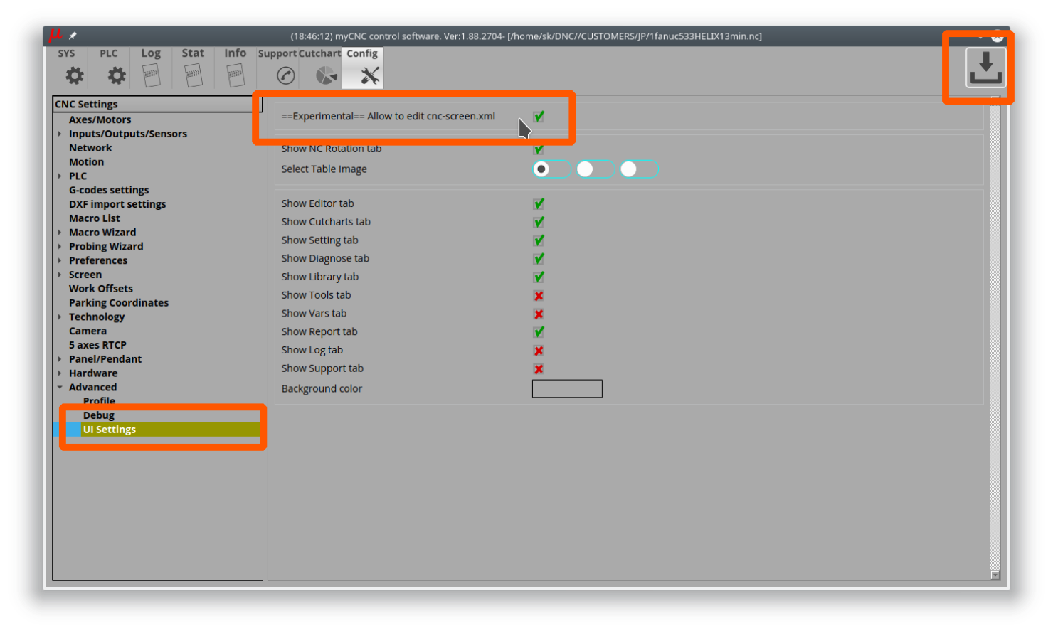
- Find the button you need to check and press the right mouse button on it
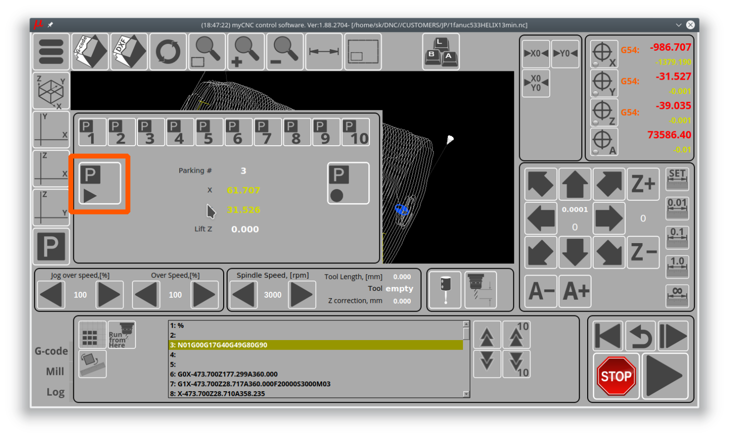
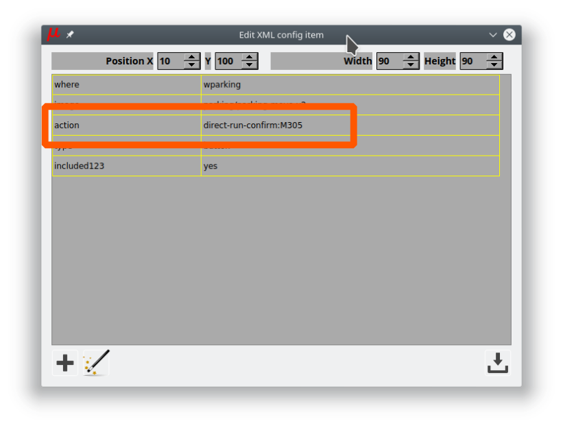
- Edit XML config item experimental dialog will be shown
- Find a line with the “action” attribute - this line indicates what action will be run when the button is pressed. In this case, the button will run the M305 macro.


For on-screen elements other then buttons, the process is similar. For example, if we would like to check how the “Lift Z” element is displayed in the parking widget:

- Go to Config > Advanced > UI Settings
Enable Allow to edit cnc-screen.xml checkbox, Press “Save” button - Find the on-screen element you would like to check and press the right mouse button on it
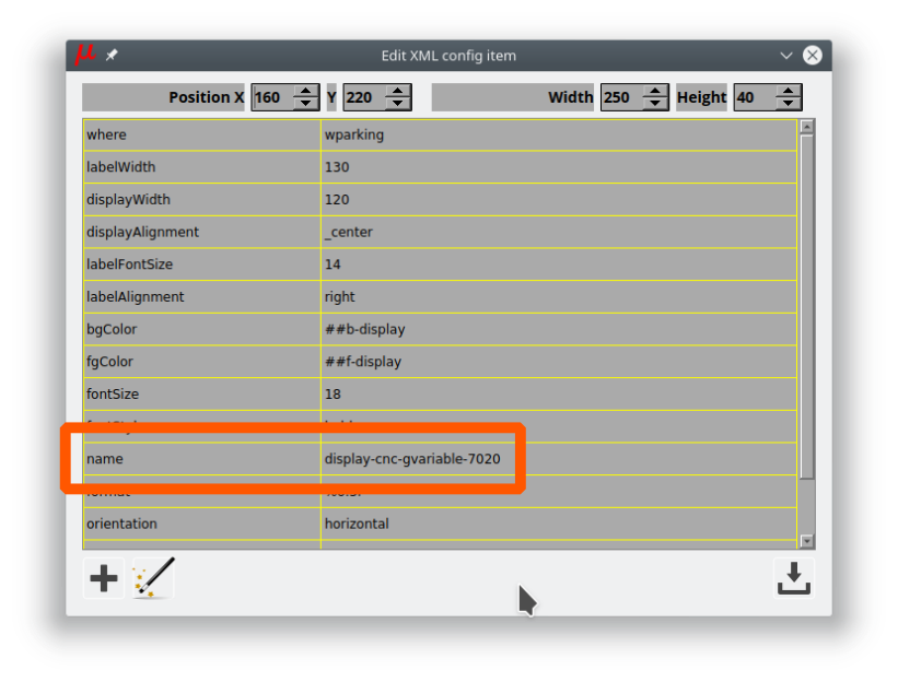
- Edit XML config item experimental dialog will be shown.
- Find a line with attribute “name” and check what value this on-screen element displays. For example from the screenshot, the on-screen element will display the value of the Global Variable #7020 (which is used as the Lift Z value in the “Go to Parking Position” macro M305).

How does the Run from Here procedure work?
In an event of an emergency stop or failure of a mill machine running a program file, it is often useful to be able to open the file back up afterwards and be able to continue from the middle of the program without having to go through all the steps again. This is often complicated by the fact that a large program file consists of many lines of code, making it difficult to easily navigate to the place where the cutting process stopped initially. In order to facilitate finding this spot, the Run from Here process is put in place in myCNC software.
The Run from Here method is described in the following section of the myCNC Screen manual: manual link
What's the difference between axes and motor outputs?
The difference between motors and axes is that multiple motors can be used for the same axis. For instance, a gantry may use two motors for the two sides of the machine during the alignment, however they are both still considered to be the “X” axis. This concept of multiple motors being used for the same axis is illustrated in detail in the Gantry Alignment manual.
If a “dual axis” is required, then you can assign a specific axis (for instance, axis Y) to two motors. This “slave Y” setup is illustrated in the following section of the manual: MyCNC Setup Examples: How to setup dual axis. Similarly, if you have multiple motors for the Z axis, they will still all be assigned to axis Z, and not to some other axis.
For tool change macros (M6) you'd need to move one motor to some parking location and switch the Z axis to a new motor output. This change between different motor outputs is illustrated in the following example: MyCNC Setup Examples: How to set up a multi-tool router
A visual way of thinking about the concept of switching motors is to imagine that one needs to draw a coloured picture (control program) on a piece of paper (working material) with six different coloured pencils. Such an operation does not require for the artist to have six different arms to complete - instead, one arm (one axis) should be enough. All that is required is to switch the pencils (different motors) by leaving them on the side of the table in some sort of a “parking location” before moving on to the next colour.
Hardware Setup and Troubleshooting
Why is there no connection between my computer and the myCNC controller?
If there doesn't seem to be any connection between the controller and the computer running the myCNC software after the computer and the controller have been connected by an Ethernet cable, check that the controller IP address has been specified correctly in the Settings > Config > Network > Controller IP address field. If that address is specified correctly, go through the No Connection troubleshooting manuals for your system: No Connection between myCNC controller and a Host computer - these manuals will indicate how to set a static IP address on your computer to be in the same subnetwork as your controller. Note that if your WiFi is in the same subnetwork, it might lead to issues with computer-controller communication - try disabling the WiFi if the issues persist.
Why do ports turn on/off automatically when opening and closing the program?
Check the _HANDLER_INIT and _HANDLER_EXIT Software PLCs for the starting and closing commands respectively (specifically, the portset and portclr commands:

The portset command activates a certain port (for example, portset(3) will activate output #3), while the portclr command clears the specified port (portclr(3) will turn off output #3). In order to disable these commands, either delete them from the relevant Software PLCs, or comment them out by putting two forward slashes in front of the commands. Don't forget to press the Save All and Build All buttons to make sure that the changes take effect.
Why is the tool change macro M6 not working?
Check that the M6TXX tool change commands are accepted by the myCNC software (Settings > Config > G-codes settings > Tool Change M6TXX):

Why is the machine not moving despite the on-screen coordinates changing?
If after the motors have been connected, the machine isn't moving despite the on-screen coordinates changing while pressing the jog keys, the pulse width might be set up incorrectly, causing the motors to not register the signals sent from the controller. The exact pulse width is different for every motor, so it is not possible to preset a default configuration which will suit every machine. Check the guide on setting up the pulse width in this manual: MyCNC Pulse Width Setup
Typically, if using a stepper motor, a higher setting number than the default should be chosen in order to allow the machine to register the pulses sent to it.
NOTE: The first value in the Pulse Width field in the myCNC settings refers to the first four movement directions for the controller (for example, X+, X-, Y+ and Y-), while the second value refers to the last two movement directions (for example, Z+ and Z-). Typically, these fields should be set to the same value, however they can be different if different drivers are used on the last two axes (motors 5 and 6) as compared to motors 1 through 4.
How does encoder resolution work in myCNC?
On modern servo drivers, the motor encoder connects directly to the servo driver and does not connect to the myCNC controller. Therefore, the encoder system, whether the encoder is absolute or incremental, the encoder resolution, etc, do not matter for the controller itself.
The servo driver has outputs for emulation of the incremental encoder ABZ. It is these signals that should be sent to the controller to obtain information about the rotor's position.
Within myCNC, the resolution (number of pulses per revolution) is usually a parameter of the servo driver that can be adjusted, and therefore is not directly related to the physical resolution of the actual encoder.
What to do if it seems like there is something wrong with the hardware?
First of all, go through the relevant hardware troubleshooting checklist available here: Hardware Troubleshooting Checklist
If using an ET10 board, check that it was assembled correctly, using the below images as reference:

A common mistake with the ET10 boards is not aligning the board properly before putting them back together, resulting in a dysfunctional assembly.
If nothing comes up, write to us using our Contact Us page. If the product is under warranty, we will replace it.
Why does the Parts Library not show certain parts?
When entering the Parts Library, you may be greeted with an empty page, or a page that's missing some parts that are supposed to be there:

To remedy this, head into Settings > Config > Preferences > Shape Library Settings and make sure that the necessary libraries are selected by clicking the checkmark field. This setting is present to allow the operator to disregard all the part libraries which are not necessary for their particular machine:

Note that the libraries must be present within the opt/USERNAME/lib folder (typically, opt/mycnc/lib) for them to be visible within the myCNC software:

Save the settings and reload the myCNC application, and the Parts Library should be back to normal:

Why do ClearPath drivers not work out of the box?
ClearPath drivers will not out of the box unless using the line driver to 5V converters. Here is the official explanation from the ClearPath website as to why the ClearPath drivers are not directly compatible:
![]()
Effectively, a converter board is necessary to create a steady 5V signal which the ClearPath driver will be able to register. These line driver to 5V converter boards are available as part of certain kits on the myCNC Online Shop.
More information about the converter boards is available here: Line driver to 5V converters.
What is closed loop control and how to set it up?
The closed loop feedback control is typically already implemented in the pulse-dir servo drivers that the machine is using, and is thus already optimized for operation with the motor. In most cases, it is impractical to interfere with its operation. If a closed-loop option is required within the controller, there are 2 main options:
- Install encoder rails and set up a second feedback loop to compensate for mechanical play. This is typically suitable for smaller milling and turning machines with strict accuracy requirements. It is impractical to install this for plasma/gas cutting machines, as the dimensions are larger and the relatively high degree of precision is not required.
- Connect the encoder outputs from the driver to the controller and display the actual position (along with what the controller thinks is the current position) on the screen, stopping operation in case of a discrepancy between the actual and set positions.
For more info on closed loop setup, see the following manual: MyCNC closed loop configuration
Plasma
What to do when the THC (Torch Height Control) system isn't working?
A full THC troubleshoting guilde is available here: THC Troubleshooting
In summary:
- Check that the THC has been enabled in Settings > Config > Technology > THC

- Check that the ADC channel number has been specified correctly for THC feedback

- Check that the reference voltage has been chosen correctly

- In Settings > Config > Technology > THC, check that the Alarm Arc Voltage Difference and Alarm Arc Voltage Rise aren't set to a value that's too low - in cases where the difference between reference and measured voltage is too great, a small value of the Alarm Arc Voltage Difference will prevent the THC system from starting. Set the value to 1000 to temporarily disable this feature.

- Check that THC is enabled in the User Settings

How does the Back to Path button work?
The Back to Path setup is described in detail in this section of the Configuration Dialogs manual.
A video showing the setup process for the Back to Path macro through a dedicated macro wizard is available here:
In general, the Back to Path button is generally used on plasma machines, while the On-Start/On-Stop behaviour (which can allow for a similar setup) is used for mill profiles.
Tangential Knife
Why is the knife not turning when using the Tangential Knife profile (X1366V)?
Check that the tangential knife is turned on in the settings. Alternatively, check that the knife is assigned the correct tool number in the DXF file import window - the tangential cutting control turns on for specific tools such as knife, half-knife and creasing wheel, and turns off for tools such as marker and camera. If an incorrect tool is assigned to a certain path during the DXF import, that tool might be one of the ones which do not require tangential cutting control to be enabled.
The M6 macro contains the commands to turn the tangential cutting function on and off. It is possible to check which tools are currently assigned to use tangential cutting in case that's necessary:

A full manual on tangential cutting control is available here: Tangential Cutting Setup
How does the M309 (Remove Whole Turns) macro work?
The macro to remove whole turns from the rotation axis prior to beginning movement is described in depth here: Rotate A axis to 0 position. The manual described the reset for the A axis, however the C axis reset when using a tangential knife is similar (both are rotating axes which can have their full 360 degree turns removed automatically prior to the program start to save the time which would have been spent rewinding the axis back to the 0 position).
Related articles:
FAQs for obsolete boards/software
How to install myCNC on Cubieboard2?
1. Number of packages are needed to run myCNC sofware on Cubieboard2. To install it run - sudo apt-get update sudo apt-get install ffmpeg libsdl1.2debian libopencv-dev libusb-1.0
2. Download myCNC-arm-linux last distribution file from download page.
3. Run the file with administrator rights:
sudo ./myCNC-arm-linux-1.84.907-2014-1204.sh
4. Press Y <Enter> to confirm you like to install myCNC software.
5. Press Y <Enter> to accept EULA terms.
6. Enter myCNC destination folder (“myCNC” by default). The software will be installed on “/opt/YOUR_FOLDER”
7. Installation will be finished in a few seconds.
8. To run the myCNC software use script file myCNC.sh in myCNC folder.
How to set up the controller IP via command line?
In command line while starting myCNC software with option “-L” For example, Linux:
./Linux/myCNC -dUt -pVision -L192.168.0.178
Windows:
c:\MyCNC\bin\myCNC.exe -dUt -pVision -L192.168.0.178
Command line option “-L” have higher priority. IP address with “L” otion is used first.
However when “Save” button in configuration dialog pressed, myCNC software reloads settings from configuration file and data from Configuration dialog/“Network” tab takes effect.
If you have different IP address settings in “Network” tab and command line “L” option - you will get connection lost (established) when “Save” button pressed.
How to transfer a profile to a different machine through Profile Archive
myCNC can store current profile snapshot to mySQL database file. This file can be transfered to another computer and profile restored form the archive.
By default database file is stored in -
“C:\MyCNC\db\profiles.sqlite” (for MS Windows)
“/home/USER_NAME/myCNC/db/profiles.sqlite” (for Linux)
To store current profile press “Ctrl+Z”. Profile save dialog will be shown. You can enter comments and enter/change save date to easy identify the shapshot later:

How to change the scale of a G-code program via Server API?
There are 2 version of command “SetScale” in the Server API to change scale of given g-code file.
For both commands g-code program should be loaded to myCNC by runnig command “ProgramFileOpen” - Example:
ProgramFileOpen /sk/DNC/3d3.nc
1) Command “SetScale”.
Format: SetScale <scale> Example:
SetScale 3.5
(myCNC software will open g-code file defined by command “ProgramFileOpen”, scale it to factor 3.5 and load result to myCNC memory).
If “SetScale” command used several times, previous “scale” ratios are ignored. myCNC software uses original g-code file and the last “scale” ratio to generate scaled program.
{avsplayer videoid=1}
2)Command “SetScale++”.
For some applications “scale” ratio should be used together with g-codes rotation. In this case commands “SetScale++” and “SetRotationAngle++” should be used.
When running “SetScale++” command “scale” ratio is latched to 'Scale&Rotation“ structure. If running “SetRotationAngle++” myCNC software loads g-code file, given with “ProgramFileOpen” commands and perform rotation and scale with given Angle and Scale.
Example:
SetScale++ 2.75
SetRotationAngle++ 1.77