This is an old revision of the document!
Table of Contents
MyCNC Setup Examples
How to setup Tangential Knife Cutting
MyCNC control has built-in tangential knife control
Tangential knife control is activated by writing “1” to Global Variable #7005 (GVAR_TANGENTKNIFE_ENABLE)
If Tangential control is activated 2D toolpath programming is enough to make tangential knife cutting. myCNC control software automatically -
- Calculates the angle of next motion;
- Lifts up the knife to safe height;
- Rotate knife accordingly next XY motion direction;
- Moves down knife on working height.
How to setup Lathe/Turning machine
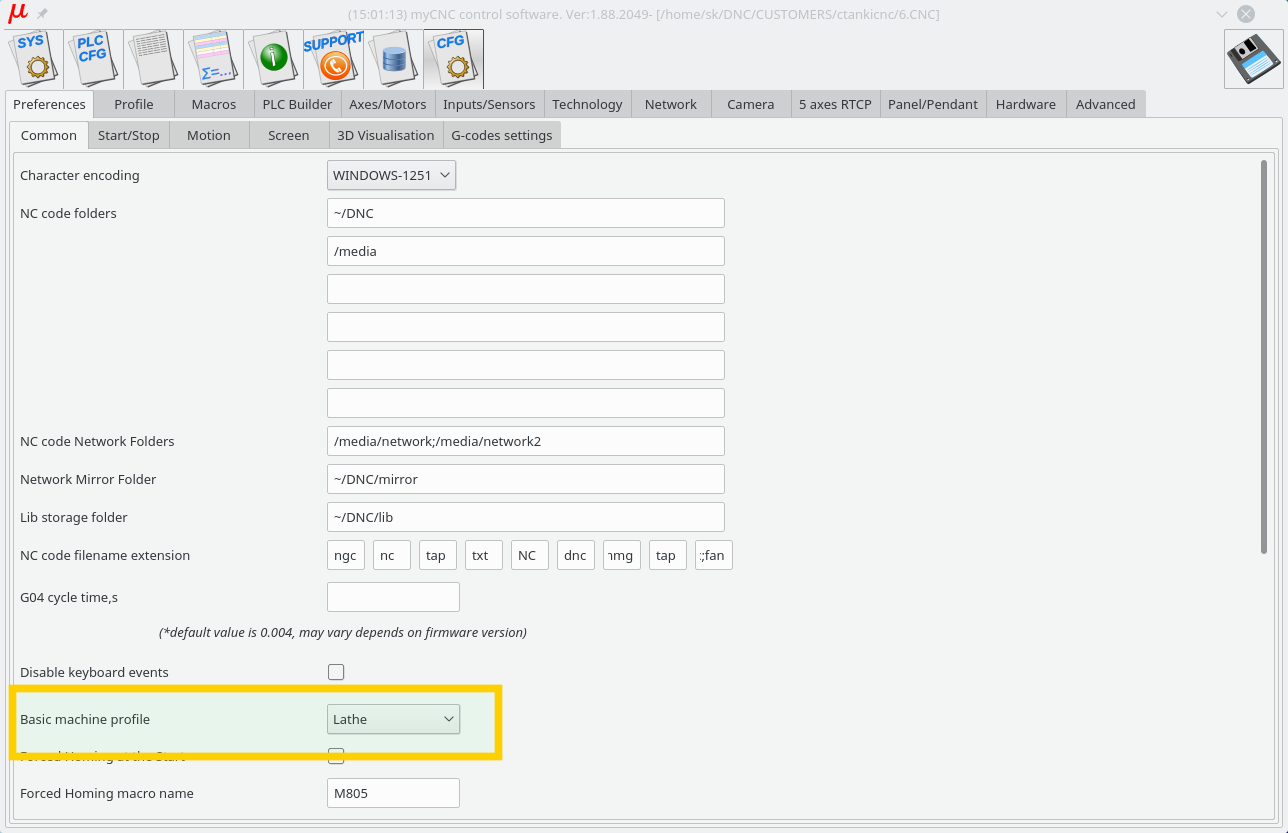
1. Select Basic profile as “Lathe” in Cfg - Preferences - Common dialog
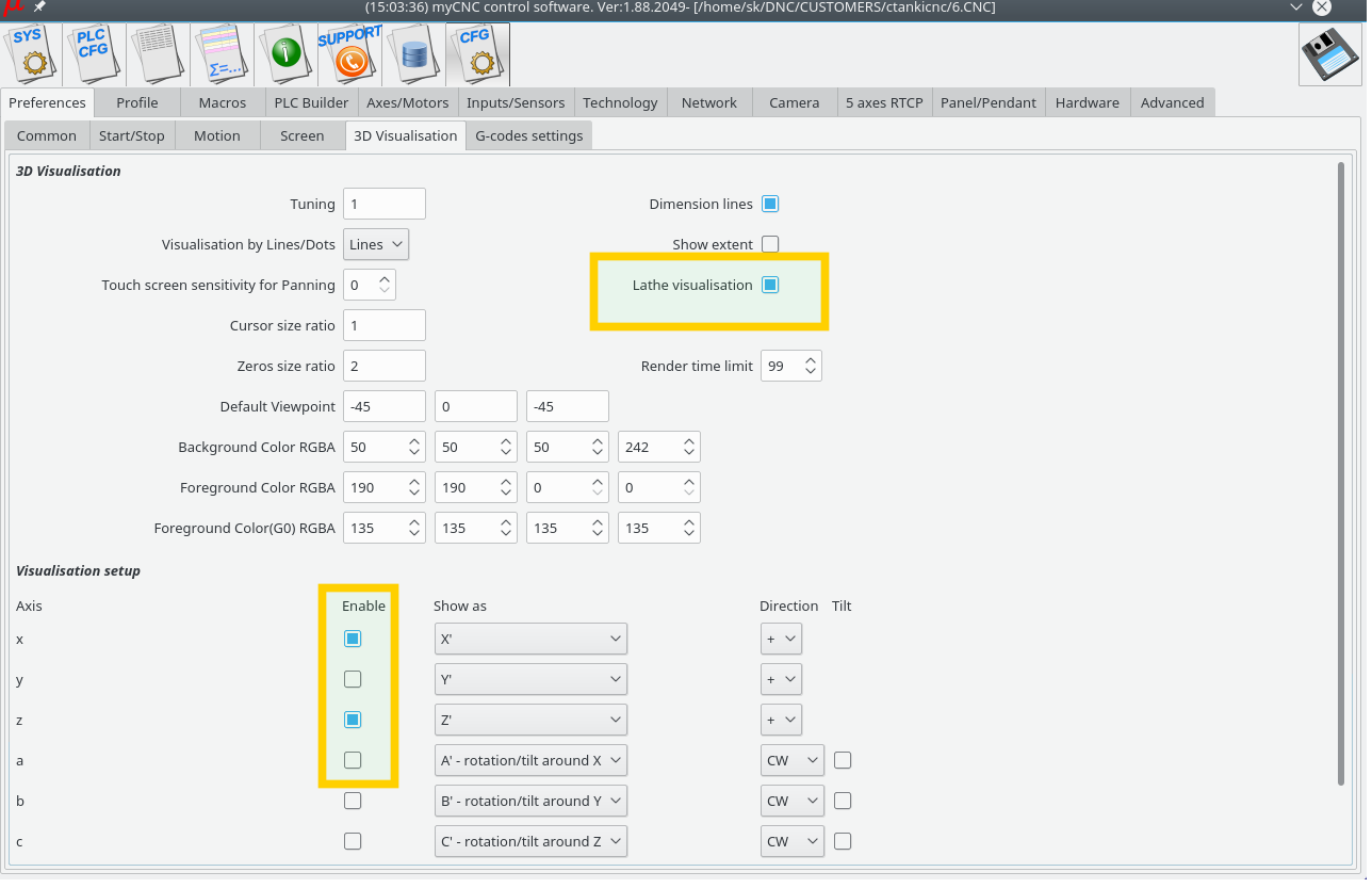
2. Select “Lathe Visualisation” in Cfg - Preferences - 3D visualisation configuration dialog
3. Select axes X, Z for visualisation and deselect the rest axes.
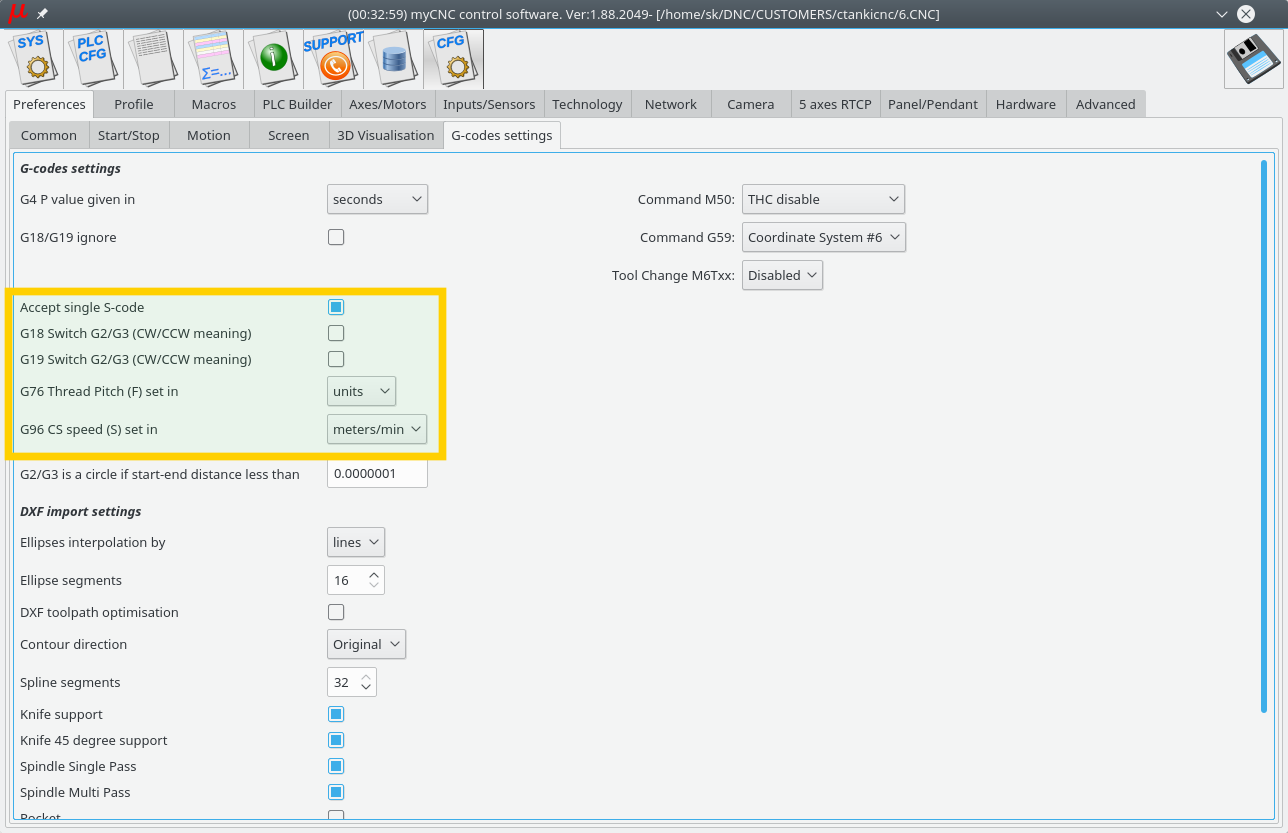
4. Check G-code settings related to Lathe operations in Cfg - Preferences - G-codes settings configuration dialog
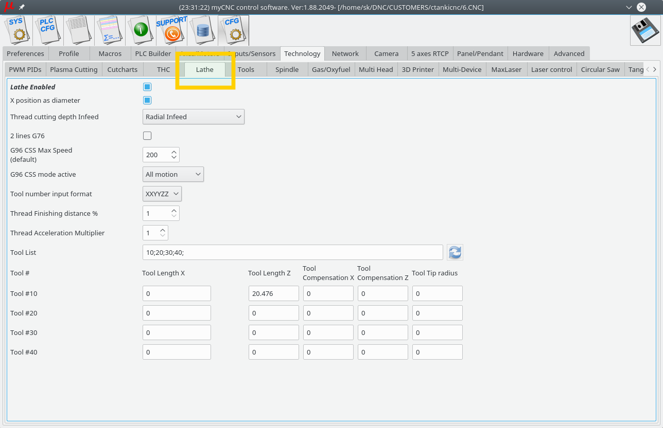
5. Goto Cfg - Technology - Lathe configuration dialog and setup appropriate settings
How to setup Multi-Tool router
We will put here some process of setup multi tool router. The router has -
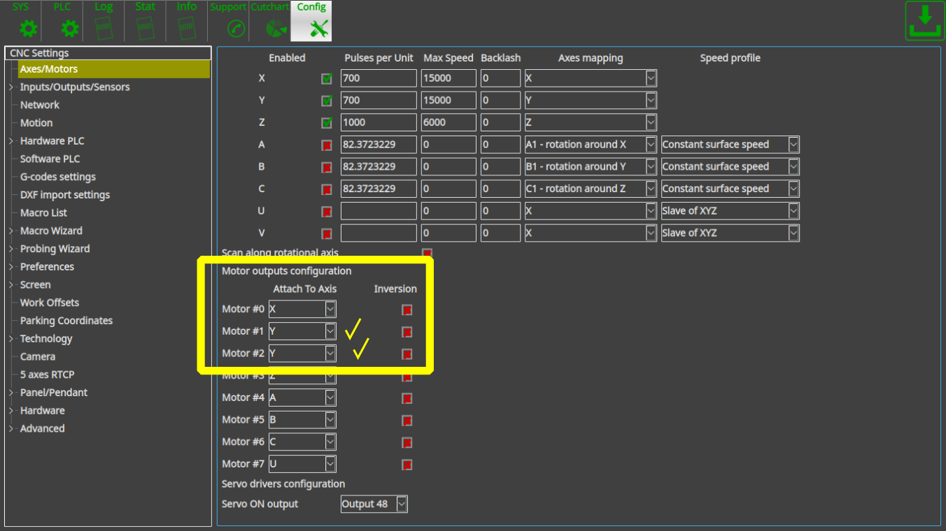
- 2x motors on X axes.
- 2x separate spindles installed on separate Z heads.
- Tangential knife head.
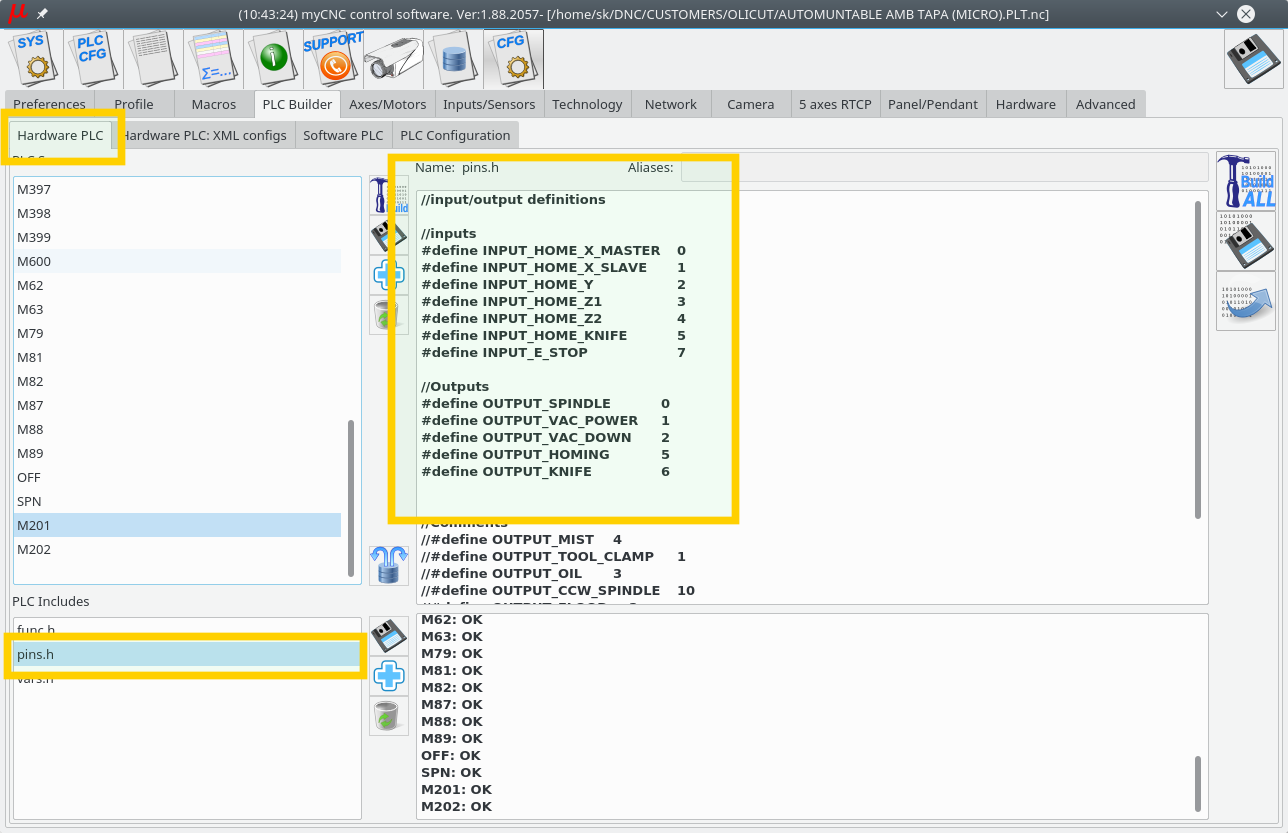
1. Inputs/Outputs assignment described on “pins.h” include file in Hardware PLC Builder area -
- pins.h
//input/output definitions
//inputs
#define INPUT_HOME_X_MASTER 	0
#define INPUT_HOME_X_SLAVE 	1
#define INPUT_HOME_Y 		2
#define INPUT_HOME_Z1 		3
#define INPUT_HOME_Z2 		4
#define INPUT_HOME_KNIFE 	5
#define INPUT_E_STOP 		7

//Outputs
#define OUTPUT_SPINDLE		0
#define OUTPUT_VAC_POWER	1
#define OUTPUT_VAC_DOWN		2
#define OUTPUT_HOMING 		5
#define OUTPUT_KNIFE 		6
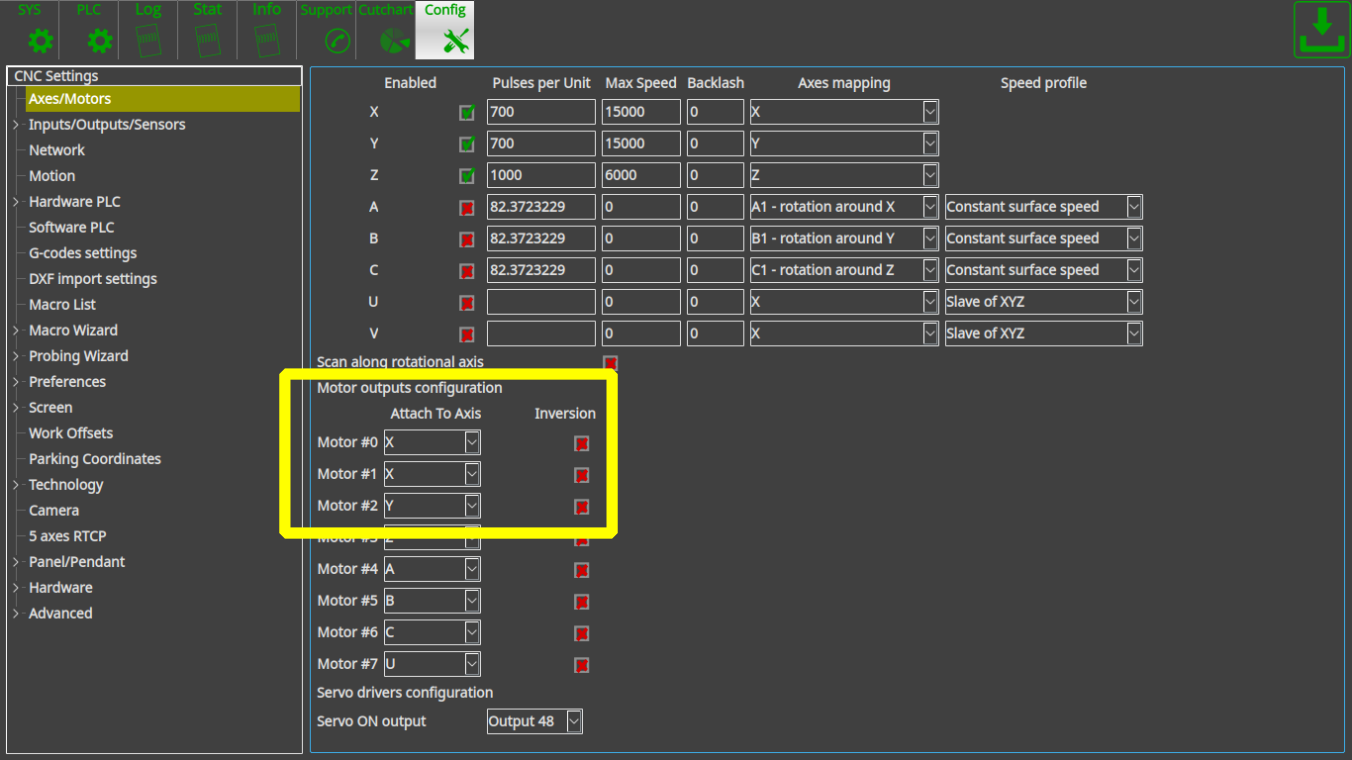
2. How to switch between spindles (Z1/Z2) heads.
Axis pulse-dir signal can be connected/disconnected from Motor output by writing to CNC registers 0x70…0x75 (112…117)
- 0x70 (112) - Motor output #0
- 0x71 (113) - Motor output #1
- 0x72 (114) - Motor output #2
- 0x73 (115) - Motor output #3
- 0x74 (116) - Motor output #4
- 0x75 (117) - Motor output #5
Low 4 bits (0..3) of the writing value represent Axis to connect -
- 0 - X
- 1 - Y
- 2 - Z
- 3 - A
- 4 - B
- 5 - C
- 15 - disconnected
pulse-dir Direction will be changed (DIR signal inverted) if Bit #4 is set.
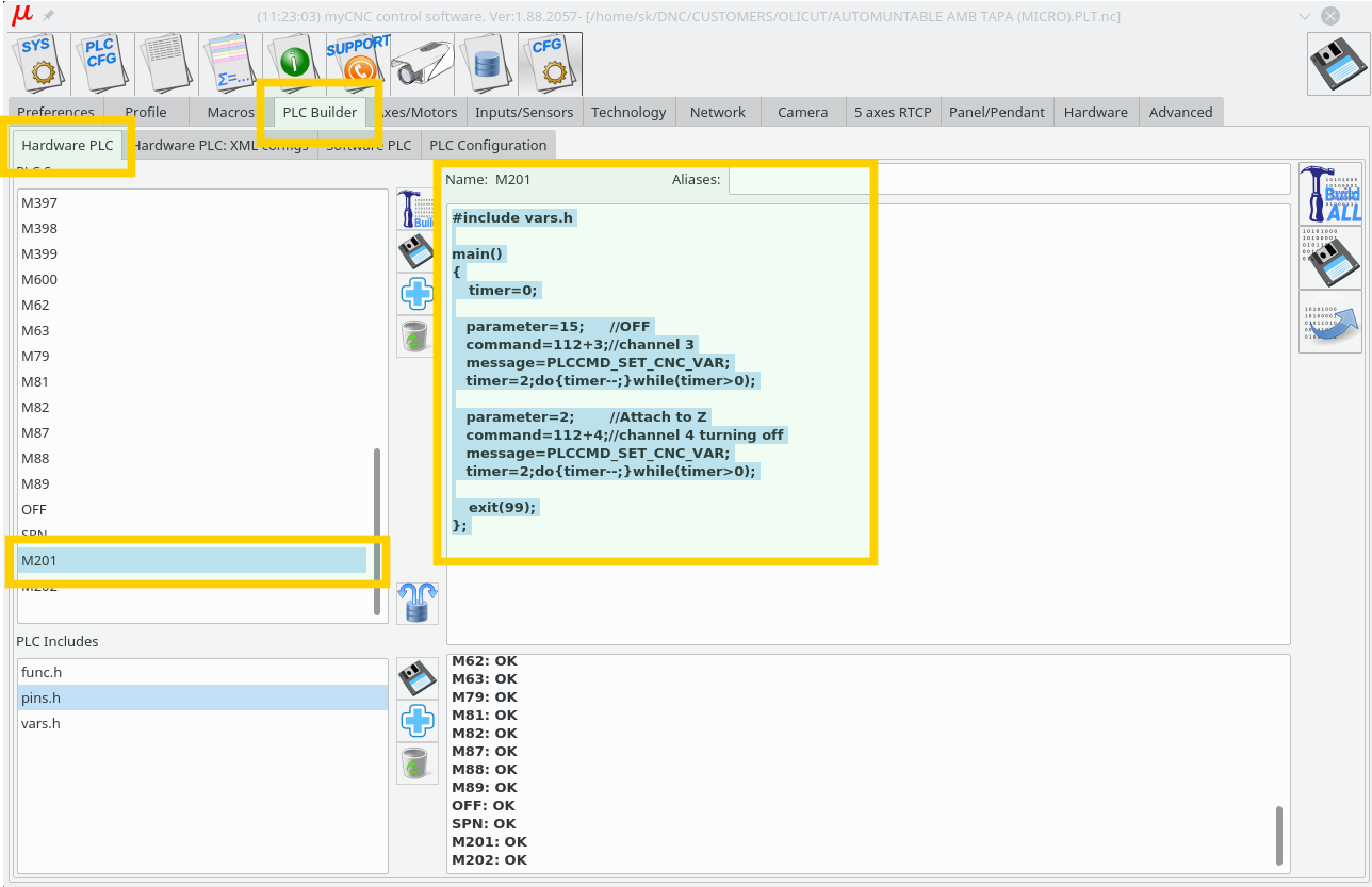
This way we add PLC procedures M201 and M202 to switch Z axis between Motor outputs #3 and #4
- M201.plc
#include vars.h
main()
{
  parameter=15;   //OFF
  command=112+3;  //channel 3
  message=PLCCMD_SET_CNC_VAR;
  timer=2;do{timer--;}while(timer>0);

  parameter=2+16;	   //Attach to Z
  command=112+4;   //channel 4 turning off
  message=PLCCMD_SET_CNC_VAR;
  timer=2;do{timer--;}while(timer>0);

  exit(99);
};
- M202.plc
#include vars.h
main()
{
  parameter=15;   //OFF
  command=112+4;  //channel 4
  message=PLCCMD_SET_CNC_VAR;
  timer=2;do{timer--;}while(timer>0);

  parameter=2+16; //Attach to Z
  command=112+3;  //channel 3
  message=PLCCMD_SET_CNC_VAR;
  timer=2;do{timer--;}while(timer>0);

  exit(99);
};
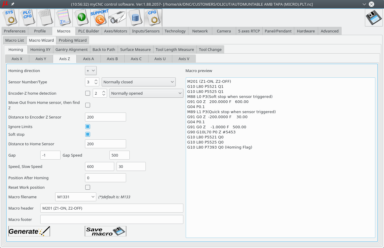
3. Homing for Z1, Z2 axes can be configured in Macro Wizard. M133 macro is usually used for Homing Z procedure. We will use macro names M1331 and M1332 for 2 homing procedures for every Z axis.
- M1331
M201 (Turn ON Z1 axis, OFF Z2 axis)
G10 L80 P5521 Q1
G10 L80 P5525 Q1
M88 L0 P3(Soft stop when sensor triggered)
G91 G0 Z   200.0000 F   600.00
G04 P0.1
M89 L1 P3(Quick stop when sensor triggered)
G91 G0 Z  -200.0000 F    30.00
G04 P0.1
G91 G0 Z     1.0000 F   500.00
G90 G10L70 P0 Z #5453
G10 L80 P5521 Q0
G10 L80 P5525 Q0
G10 L80 P7393 Q0 (Homing Flag)
- M1332
M202 (Turn OFF Z1 axis, ON Z2 axis)
G10 L80 P5521 Q1
G10 L80 P5525 Q1
M88 L0 P4(Soft stop when sensor triggered)
G91 G0 Z   200.0000 F   600.00
G04 P0.1
M89 L1 P4(Quick stop when sensor triggered)
G91 G0 Z  -200.0000 F    30.00
G04 P0.1
G91 G0 Z     1.0000 F   500.00
G90 G10L70 P0 Z #5453
G10 L80 P5521 Q0
G10 L80 P5525 Q0
G10 L80 P7393 Q0 (Homing Flag)
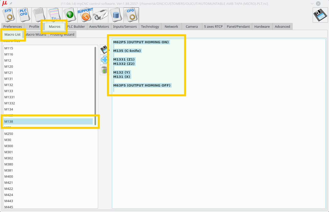
4. M138 macro is used for Home-All procedure. It should be fixed to support Z1, Z2, tangential knife homing and OUTPUT_HOMING output described in “pins.h”
- M138
M62P5 (OUTPUT HOMING ON)

M135 (C-knife)

M1331 (Z1)
M1332 (Z2)

M132 (Y)
M131 (X)

M63P5 (OUTPUT HOMING OFF)
5. M6 - Tool Change macro for multitool configuration.
- M6
M600 P#5409

if [ #5409 NE 1 ] 100
M150
GOTO 1000

N100
if [ #5409 NE 2 ] 200
M151
JUMP 1000

N200
if [ #5409 EQ 3 ] 300
G10 L80 P7005 Q0
JUMP 1000

N50
G10 L80 P7005 Q1


N300

N1000
G10 L81 P5400 Q5409    (set current tool number)

