Table of Contents
Connecting an ASDA-B2 servo to the myCNC-ET6 controller
This manual is part of the broader series of MyCNC Setup Examples. Select images are taken from the DELTA ASDA-B2 User Manual.
Connection
The connection consists of two sections - power setup and signal connection.
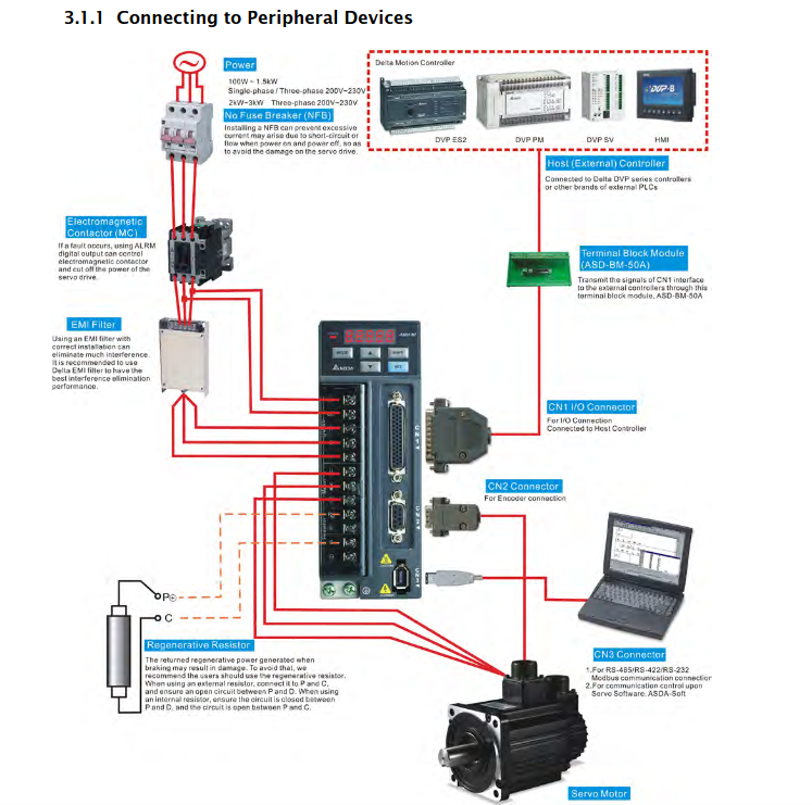
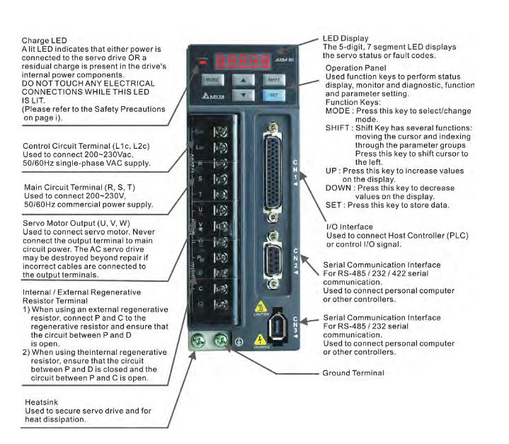
There are 2 cables from the motor to the servo drive - a power cable for powering the drive and an encoder cable. The encoder is connected to the CN2 connector, while the power one is connected to the U, V, W and GND terminals. The wires on the cable have protective covers that are stamped corresponding letters, so it should be clear which wire goes to which corresponding terminal.
The power supply of the servo drive is connected to the terminals L1c and L2c, while the power connection is done through the R, S, and T terminals. In the case of the Eastern European voltage standard (400W), the servopack is connected to 220V, in which case the R and S terminals are used. With a simplified connection, you can simply connect the jumpers from L1c to R and from L2c to S.
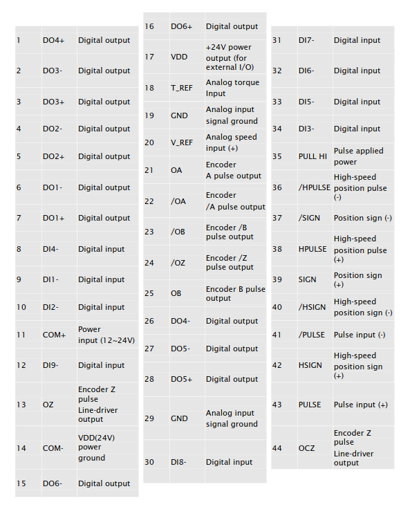
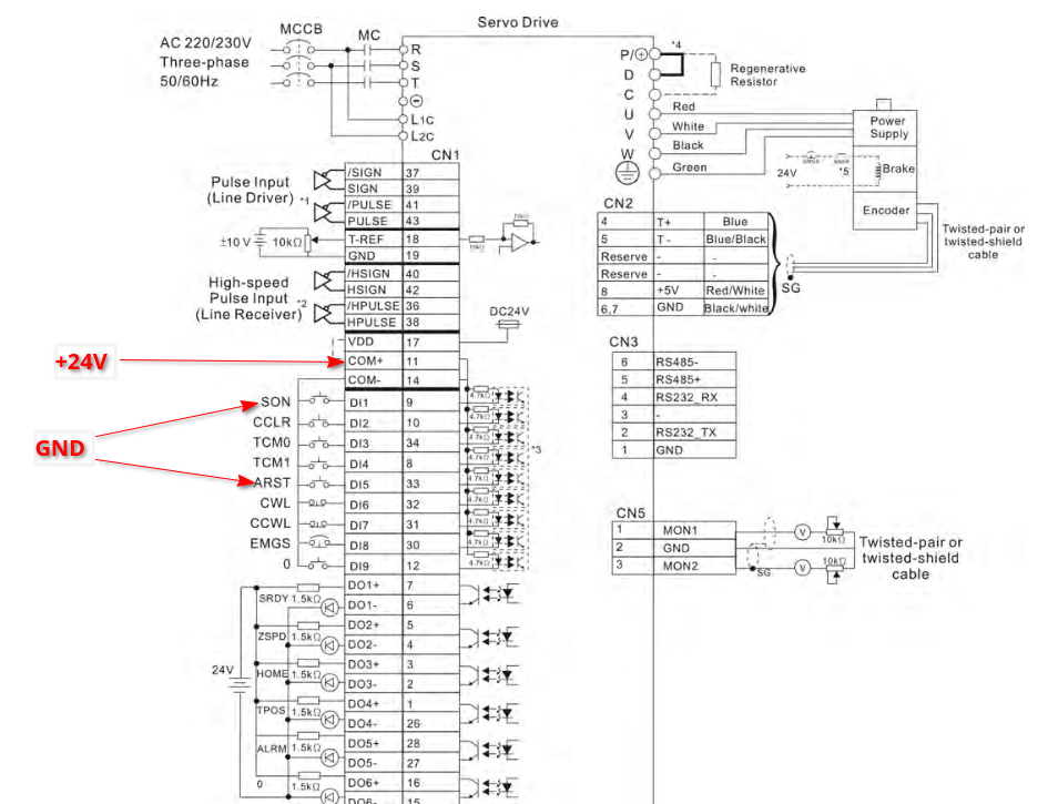
At this point, the connection of the power supply unit is complete. All further connections are made using the CN1 connector, which features the following pinout:
In general, the servo drive must be given a setpoint signal (step-dir), a servo ON/enable signal (SON), and an error reset signal (ARST). Going from the servo drive to the controller, on the other hand, is the Servo Ready signal (SRDY).
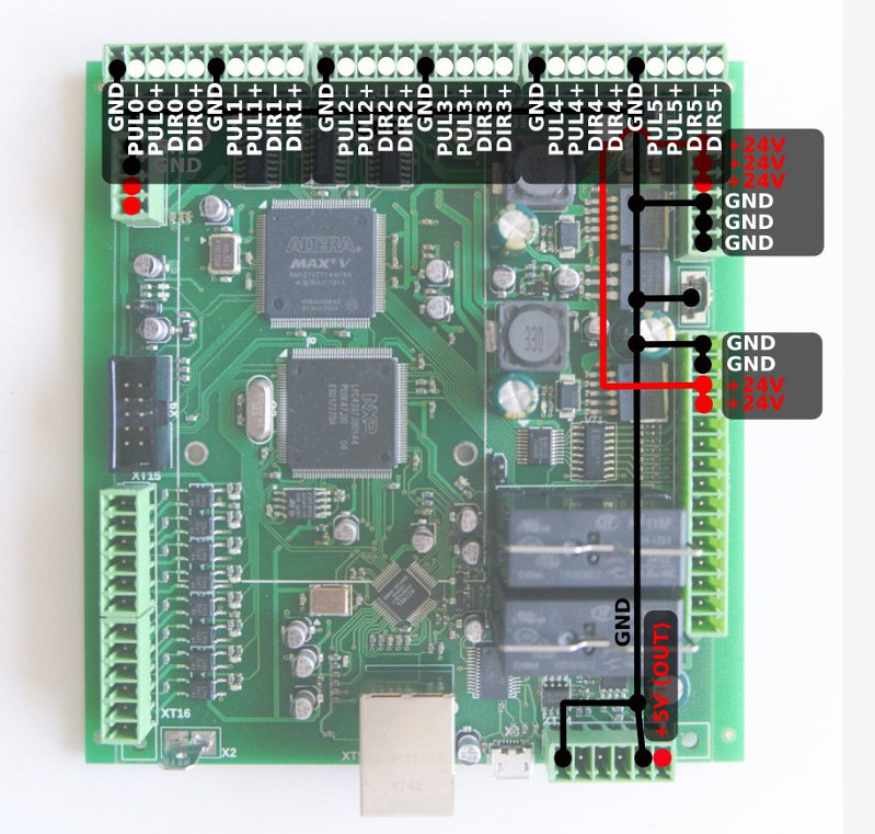
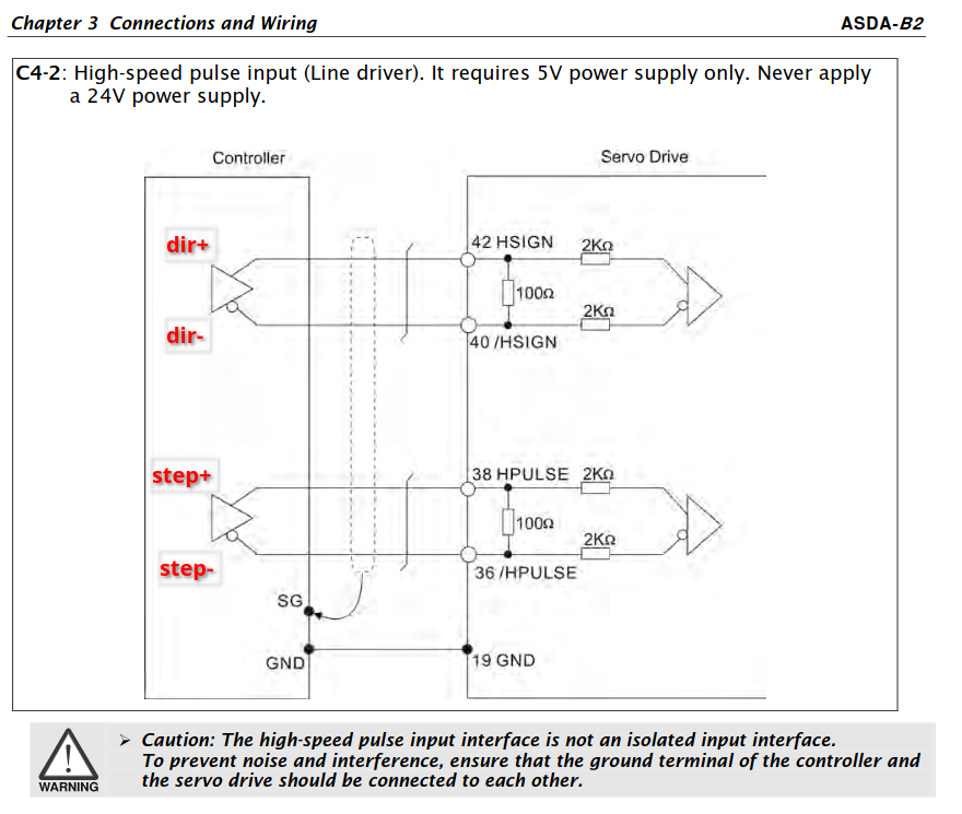
Step-dir signals are taken from the controller, using an unused connector:
In this example, we will be using the connector #5. These signals are sent to pins 40.42 and 36.38 of the CN1 connector of the servo drive.
It is also necessary to connect the GND from the controller connector to pin #19 of the servo drive.
In case of this example, 8 discrete signals can be fed into the ET6 controller, and all of them are already used on the machine, so there is nowhere to connect the Servo Ready signal. However, it is still possible to send signals to the servo drive. To do this, connect the +24V from an external PSU to pin #11, and the GND (negative terminal of the same PSU) to pins #9 and 33. Pin #9 will put the servo in the Ready mode (ready for operation), while pin #33 resets the error should one occur.
As an aside, sometimes it is not possible to reset the error using this signal from pin #33. In this case, turning off the power of the servo should accomplish the task. To do this, it is useful to power it through separately (via 6A).
There are two power supplies on the machine - one feeds only the controller and a mini-PC, the other feeds the entire 24V low-voltage machine. Therefore, it is better to take the voltage for supplying signals to the servo drive from the second PSU.
The signals themselves can be organized either through a conventional mechanical button, or by using the unused transistor outputs of the controller, but it is advisable to use the intermediate relays.
Servo Settings
At this point it is time to set up the servo settings.
The easiest method would typically be purchase a cord to connect the servo to a computer, at which point it would be more straightforward to set up. However, there exist situations where the user does not wish to purchase a separate cord (perhaps in the interests of time, if this is the only servo of this type that is used in the shop, etc). In such a scenario, it is technically possible to enter the settings using the buttons on the servo drive panel - this will however be a more laborious process.
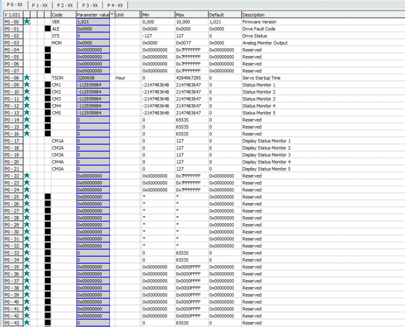
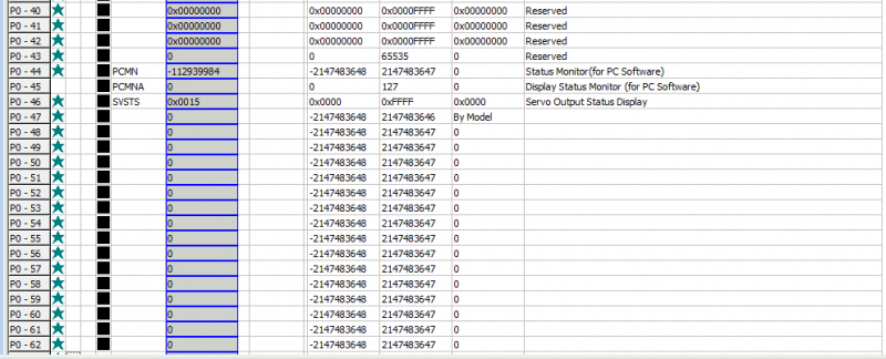
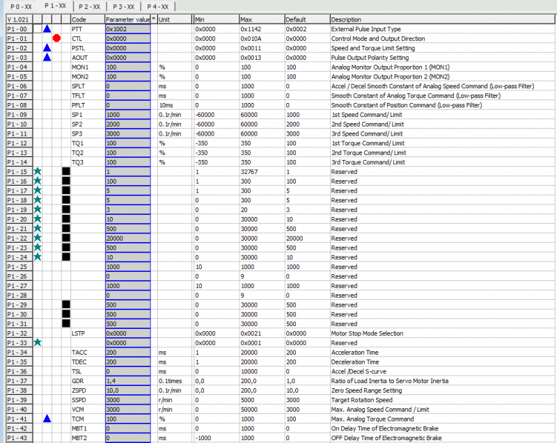
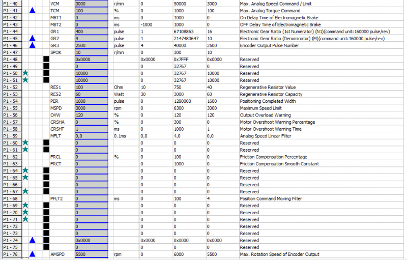
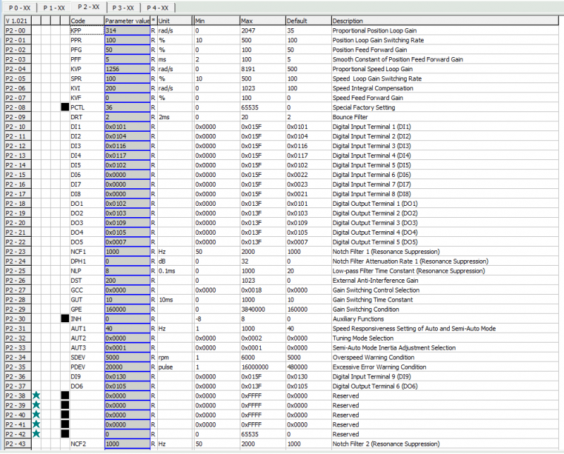
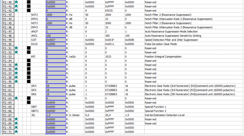
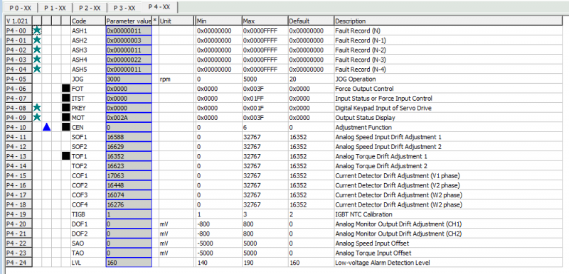
Below are the screenshots of the settings provided to the myCNC team by one of our long-term clients. It is necessary to go over the menu of the servo drive and change the items that differ from the values below.
NOTE: There are parameters in this menu that cannot be changed, as well as parameters that are not recommended to change manually. It is therefore highly recommended to check the manual prior to entering any changes to these parameters. The myCNC team provides the list below for convenience only.
In general, the following sections of the menu need to be checked:
- settings related to the inputs and outputs of the servo drive;
- operating mode settings (position control);
- PID settings and resonance frequencies;
- settings of the electronic gearbox.
At this stage, go through the parameters on the servo drive using the list below. If the parameter values differ from those in the list, consult the manual for the parameter description. If the parameter belongs to the servo settings, it will most likely need to be changed. If the parameter is informational, then it is possible to skip it and move on.
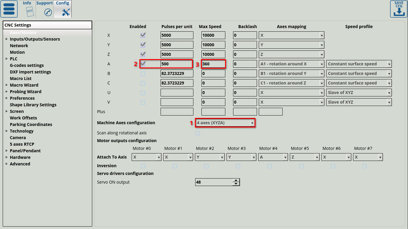
Next, within the myCNC software, to the Axes/Motors config section andenable the 4-axis configuration (1), check the “A axis” box (2), and then set the value 500 in the field next to it. Set the value of the maximum speed (3) (for better results, limit it to 360 rpm rather than a higher value). After the settings have been entered, press the Save Cfg button in the upper right corner.
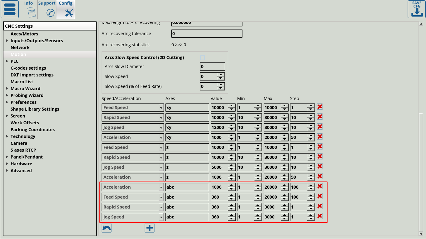
Go into the Motion tab and enter the parameters for “abc”. The acceleration value can be left at 1000, while the feed, positioning and manual speeds should be set to 360.
Click the Save Cfg button and restart the program.
After these settings, the rotary axis should be enabled. You can check this by pressing the manual jog movement buttons for the A axis on the main screen.

