quickstart:mycnc-control-board-setup
This is an old revision of the document!
Setting up the myCNC control board
- Connect 24V DC power supply to myCNC control board
- Here are power-up examples for ET6, ET7, ET10 control boards
- Connect myCNC Ethernet controller with Network cable directly to Host computer or to Network Router. If use Odroid-C2 (Raspberry-Pi3) computers as a Host, Network cable is a short 0.5ft cable between Odroid & Controller

- Setup Network addresses for Host computer and myCNC Ethernet controller. Addresses of Controller and Host should be in same local network. For Example -
Controller Address: 192.168.0.78
Host Address: 192.168.0.100
or
Controller Address: 192.168.5.10
Host Address: 192.168.5.11
Look here if need to change IP address of controller board
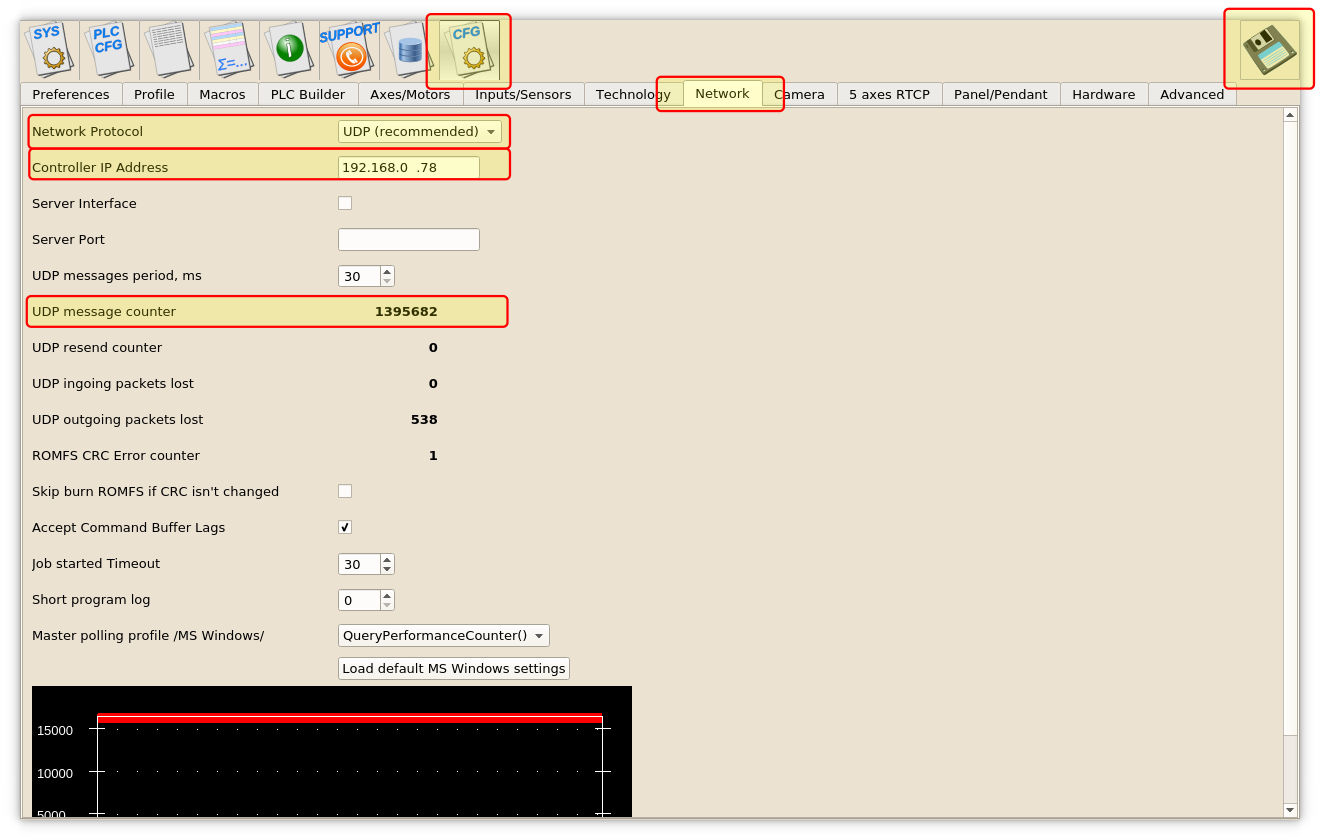
- Goto MyCNC software, Cfg Settings, Network Tab and
- Set actual Controller IP address to “Controller IP Address” to tell the software where it can find myCNC Controller,
- Set “Network Protocol” to “UDP”,
- press “Save” button on the top-right of myCNC screen.
- Changes should be applied on the fly and UDP message counter should start counting which means communication between Controller & Host works correct.
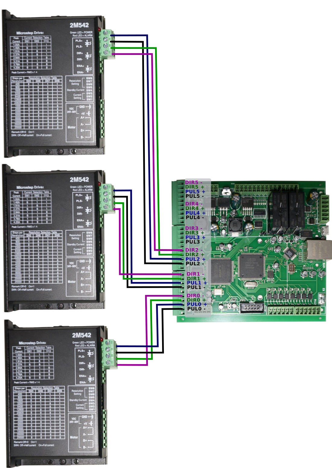
- Connect Pulse-Dir signals from servo or stepper driver to myCNC control board
- Check what minimal pulse width your drivers accept and set pulse width of myCNC control board accordingly (equal or more) in MyCNC software → Cfg Settings → Hardware Tab → Common Hardware Settings
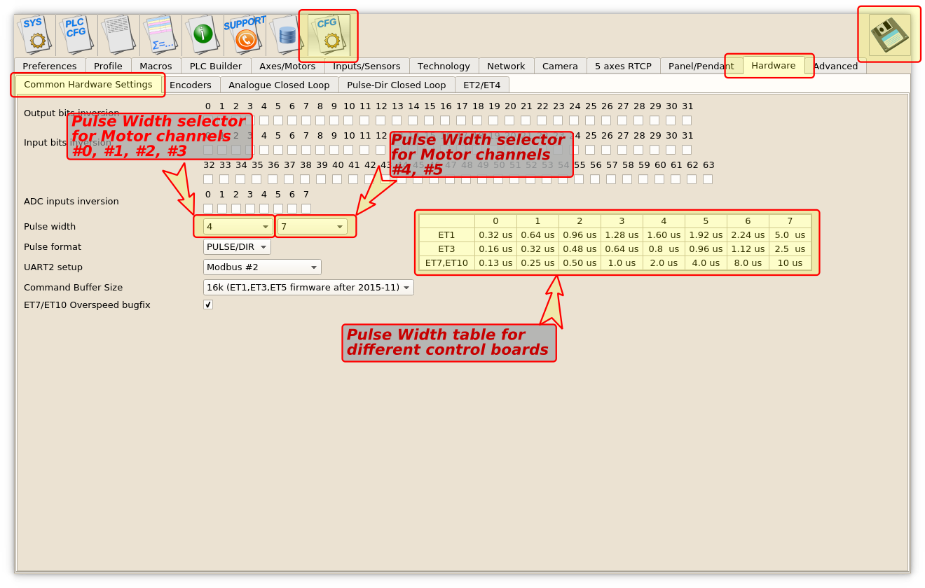 MyCNC-ET6, myCNC-ET7 controllers support separate pulse width settings for the first 4 channels (#0, #1, #2, #3) and the rest 2 (#4, #5). This option can be convenient if use high performance servo drivers with low psed stepper drivers (for example high speed servos for X, Y, Z axes and low speed stepper for rotational A axis). myCNC-ET10 controller use only the first pulse width selector for all motor outputs.
- Read more about the pulse width setup here.


quickstart/mycnc-control-board-setup.1568995088.txt.gz · Last modified: 2019/09/20 11:58 by ivan