This is an old revision of the document!
Table of Contents
MyCNC closed loop configuration
Servo ON handling
There are few ways to Enable/Disable Servo PID loops in myCNC software
1. On-Screen button. To enable/disable Servo PID control button should have actions:
action="servo-pid-on"  (enable pid)
action="servo-pid-off"  (disable pid)
For example
Buttons for Servo-ON and Servo-OFF
<gitem where="toolbar-servo" image="motor/motor-start" action="servo-pid-on"
height="80" event="pressed-delay-1000" type="button"/>
<gitem where="toolbar-servo" image="motor/motor-stop" action="servo-pid-off"
height="80" type="button"/>
Popup widget container for Servo Pid On/Off buttons
<quick-popup-layout>
<current>popup-servo</current>
<layout stretch="0" name="popup-servo" wa="80;160;right" orientation="vertical" skin="skin/metal-01">
    <widget stretch="1" spacing="0" name="toolbar-servo" orientation="vertical">myitems</widget>
</layout>
</quick-popup-layout>
Button to show containner with 2 buttons for servo-on/servo-off buttons and led to show current servo pid state
<gitem where="magic" position="960;0" width="80" height="80" image="motor/servo-driver"
action="mypopup-toggle:popup-servo" xattr="56;4;20;20;led;green;round"
address="outputs" number="47" type="xbutton" />
2. Using Global Variables API. Global variables 60000 and 60001 are mapped to turning On and Off Servo PID control.
- Write “1” to register number 60000 will turn ON Motor closed-loop control PIDs
- Write “1” to register number 60001 will turn OFF Motor closed-loop control PIDs
3. Automatic Servo ON/OFF. There are 2 handler procedures in Software PLC can be used to automatic PID ON/OFF.
- _HANDLER_INIT - procedure executed once judt after CNC control software loaded, connection with myCNC controller established and a complete configuration is sent to the controller.
- _HANDLER_EXIT - procedure executed while myCNC control software shut down process.
To handle automatic Servo ON/OFF writing to registers 60000, 60001 should be added to handler procedures. Example are below
- __HANDLER_INIT.PLC
main()
 {
  gvarset(60000,1);  //turn Servo PIDs On
  exit(99);
 };
- __HANDLER_EXIT.PLC
main()
 {
  gvarset(60001,1);  //turn Servo PIDs Off
  exit(99);
 };
Analogue -10V..+10V/Incremental encoder closed-loop setup
Pulse-Dir/Incremental Encoder closed-loop setup
Let's use Motor output #2 (configured as axis X) and Encoder #1 to build closed-loop PID control.
- Goto Encoders settings tab. If rotary encoder is used as a feedback - setup Encoder resolution for Encoder #1. For linear encoder set resolution 2500.
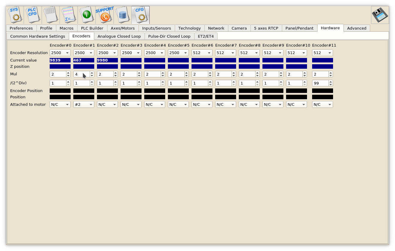
- Set Mul and /(2^Div) ratios to get result Encoder resolution equal to Pulses-per-Unit resolution. For example
Servo driver with 2500 pulses per revolution,
Electronic gears "1" and ball screw 5mm are used.
Linear encoder with 1um resolution used as a feedback.
Pulses per unit are (2500*4)/5=2000 pulses per mm
Original Linear encoder resolution (1um) is 1000 pulses per mm, need to set
multiplier to "4" and divider to "1" to get result ratio
4/(2^1)=4/2=2 and result Encoder resolution -
1000* 4/(2^1)=2000
- Set Attached to motor to “#2”
- Goto Pulse-Dir Closed Loop ang setup PID parameters for PID attached to Motor#2. The most importalt parameters are
- PID proportional ratio Kp
- PID integral ratio Ki
- PID integral limit. Integral value will be limited by given value.
- Encoder channel used as PID feedback
