Action unknown: siteexport_addpage
mycnc:jog_through_adc_inputs
Jog through ADC inputs
Main window: Basic functions:
- ADC-а device that converts the input analog signal into a discrete code (digital signal). In this case, the incoming analog signal is proportionally converted into a control signal of displacements along the selected coordinate.
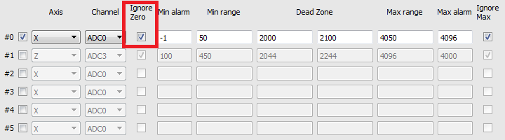
- To activate the Jog through ADC inputs, it is necessary to check the box next to number of channel:
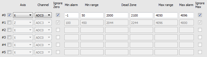
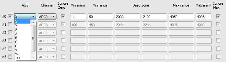
- Next you need to select the axis by which the control will be carried out using an analog signal. It is also possible to select a vertical support control system during tracking (TNC).
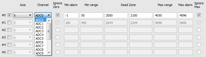
- It is also necessary to choose the number of the ADC input channel on the controller, where the analog signal from the analog control (analog-joystick) will go directly.
- The processor input is usually designed to measure an analog signal in the range of 0 to 5V. Correspondingly inside the processor, this analog signal will be converted to a digital value from 0 to 4096. Where 0 is 0V, and 4096 is 5V.


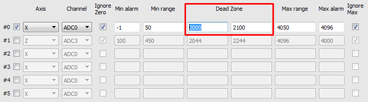
- In CNC machines, as a rule, the source of the analog signal and the main control is the joystick. The most convenient and most common are joysticks based on Hall sensors with power supply + 5V and output signals 0-2.5V-5V. Where the level 2.5B corresponds to the position of the joystick at rest, i.e. the controlled axis is not subject to control. .After converting the analog signal to 2.5V, the digital value of 2048 corresponds to the digital value of 2048. Typically, joysticks and similar control devices at the output, even at rest, have small distortions and noises in the output signal. To prevent false positives and unauthorized movements, a “dead zone” is entered in the settings.
- “Dead zone” - is set by two values of the lower and upper limit of the values of the input signal, in the range of which the system will not respond to the input signal and system movements and other reactions to the joystick will be absent. For example, the system will not perform any reactions or actions in the range of values from 2000 to 2100, which in turn corresponds to the input signal levels in the range from 2.44V to 2.56V.
- Accordingly, 0V is a movement to the left or counterclockwise, at the maximum speed and 5V is movement to the right or clockwise at the maximum speed.The value of the signal in the range from 0 to 2.5V - allows a smooth, adjustable movement to the left or counterclockwise, and accordingly the signal value from 2.5V to 5V allows a smooth, controlled movement to the right or clockwise.

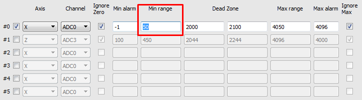
- Also in the program is designed to protect against breakage of the joystick itself or broken wires. Because when the cable is cut from the joystick to the controller input, the level of the input signal will be equal to or close to 0V (0). Also, for certain errors in the wiring, it is possible for a false alarm to occur at 5V level (4096) at the controller input. To prevent movement with such errors in the program, you can set the minimum and maximum level of the signal at the input to the controller. For example, the minimum signal level is set to 50, which corresponds to 0.06V, and the maximum level is set to 4050, which corresponds to 4.94V.


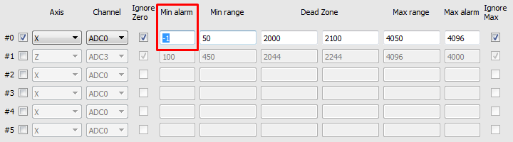
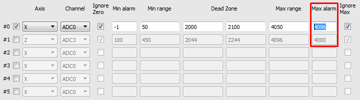
- In the program, you can simply set the alarm signal level. Two levels are set. The minimum alarm is the signal level at which the system considers that the analog control device is faulty and the Maximum alarm is the maximum level from the analog control device at which the system also decides that the control is damaged. In the example, these levels are set to -1 (0V) and 4096 (5V), respectively.


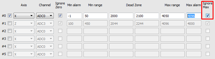
- If necessary, these alarms can be disabled by setting the checkboxes to the appropriate areas.


mycnc/jog_through_adc_inputs.txt · Last modified: 2018/09/05 16:28 by pupalaiser