Table of Contents
CAM Module
The CAM module (also known as dxf2-import, to distinguish from the dxf-import function) allows the user to import DXF files into the myCNC software. The CAM module also serves as an intermediary step between designing the files in the CAD Module and bringing them into the main screen of the software to cut. The CAM is (as of late 2025) designed primarily for plasma/laser cutting applications - for machines with applications such as tangential cutting, milling, etc, the regular dxf-import option is recommended.
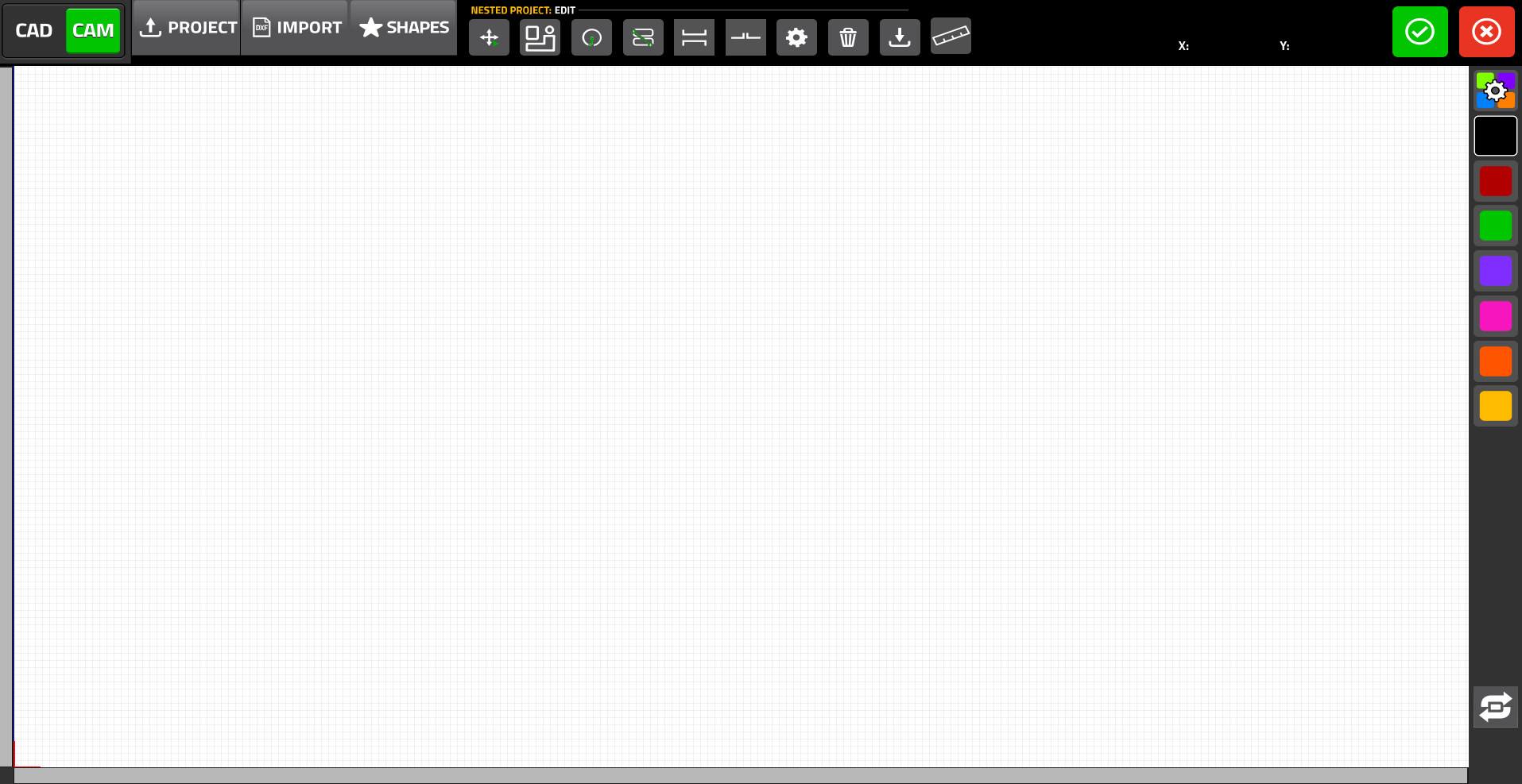
The import screen for the Import DXF button (as it appears upon opening) is shown below:
The following main options for importing files/parts into the CAM editor are available:
- CAD – design a part/file using the built-in CAD editor
- Project – import an existing project (one you've saved inside myCNC before)
- Import – import a DXF file from your computer
- Shapes – import a shape from the built-in parts library with more than 70 common parts
Additionally, the following buttons are responsible for editing the shapes that have been imported through any of the three main options listed above (Import Project, Import DXF File, and Import Shapes):
Bringing files in
Below are the main ways to bring files into a CAM project (not counting designing the file in the CAD module, which is described in its own manual).
Open Existing Project
First, let us go through the process of importing a project into the CAM editor before describing the ways in which we can edit and manipulate it.
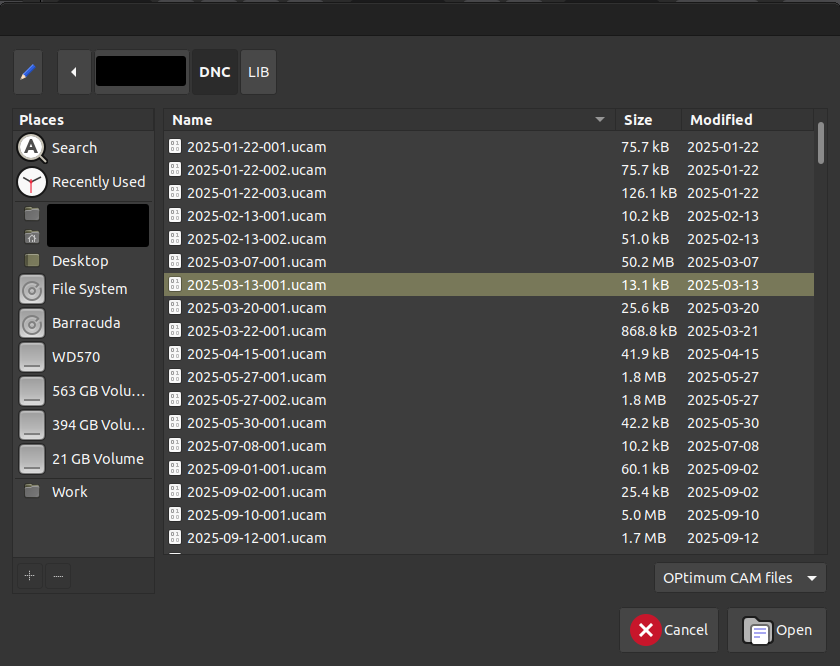
Upon pressing the Project button, a file browser will pop up, allowing the operator to select an existing project. This project is typically some file (or a number of DXF files) that have previously been imported into myCNC, arranged/edited in the CAM Editor, and then saved for later use. This manual will describe the process of saving a custom project in more detail in the following sections.
From the file picker, select the necessary project (which will have the .ucam format), and click the Open button. The project will be loaded into the myCNC editor and can be imported or manipulated/edited further:
Import DXF
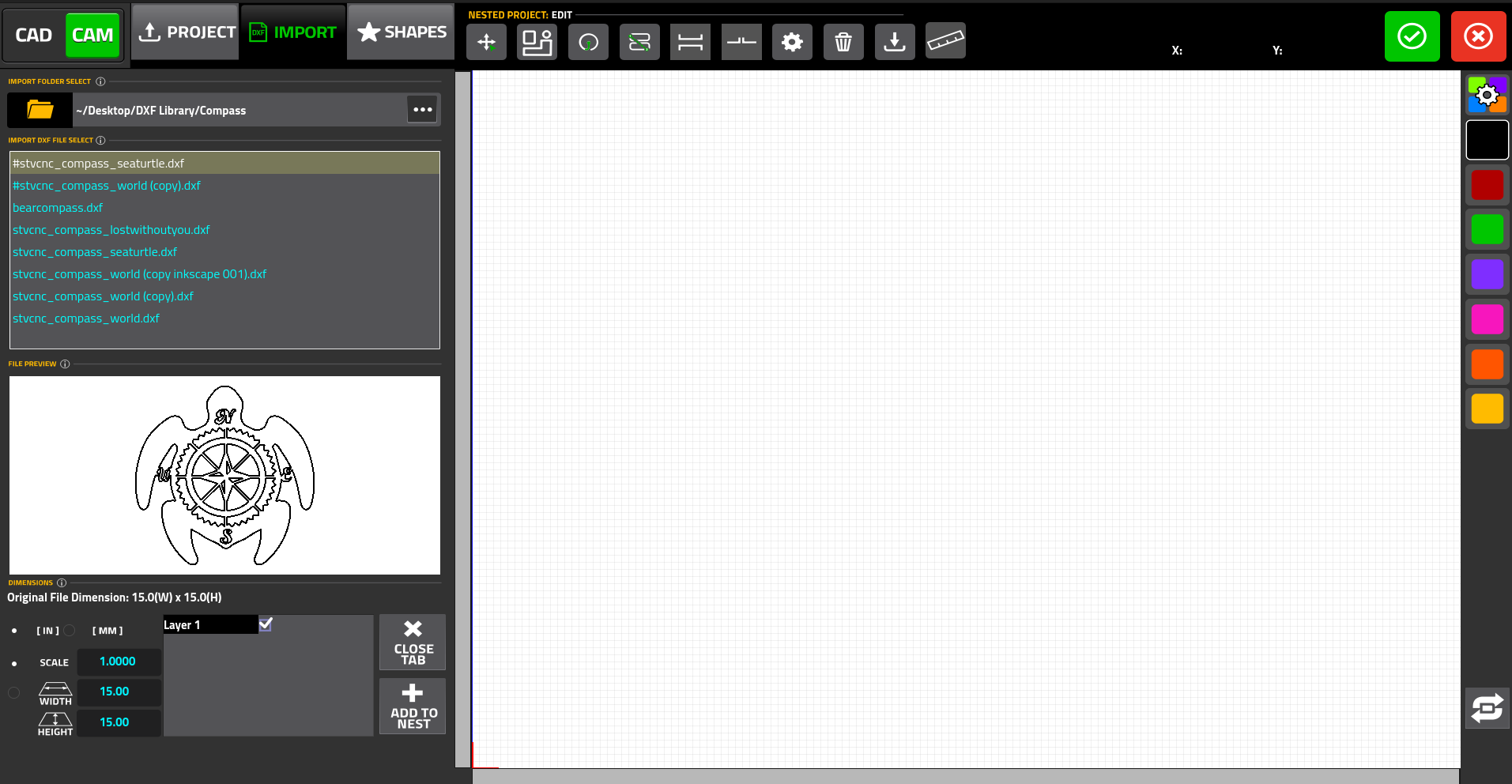
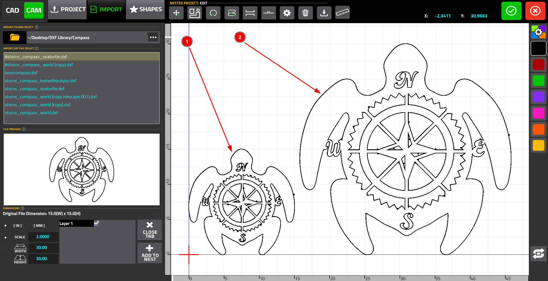
Upon pressing the Import button, a sidebar will appear on the screen:
This sidebar will allow the user to import DXF files into the editor. The components of this sidebar are listed below:
1. Current folder selection:
By default, the file is loaded from the folder specified in the Machine Settings (Machine Settings > Preferences > Common > NC Code Folders). However, the folder can also be changed using the Select Library button:
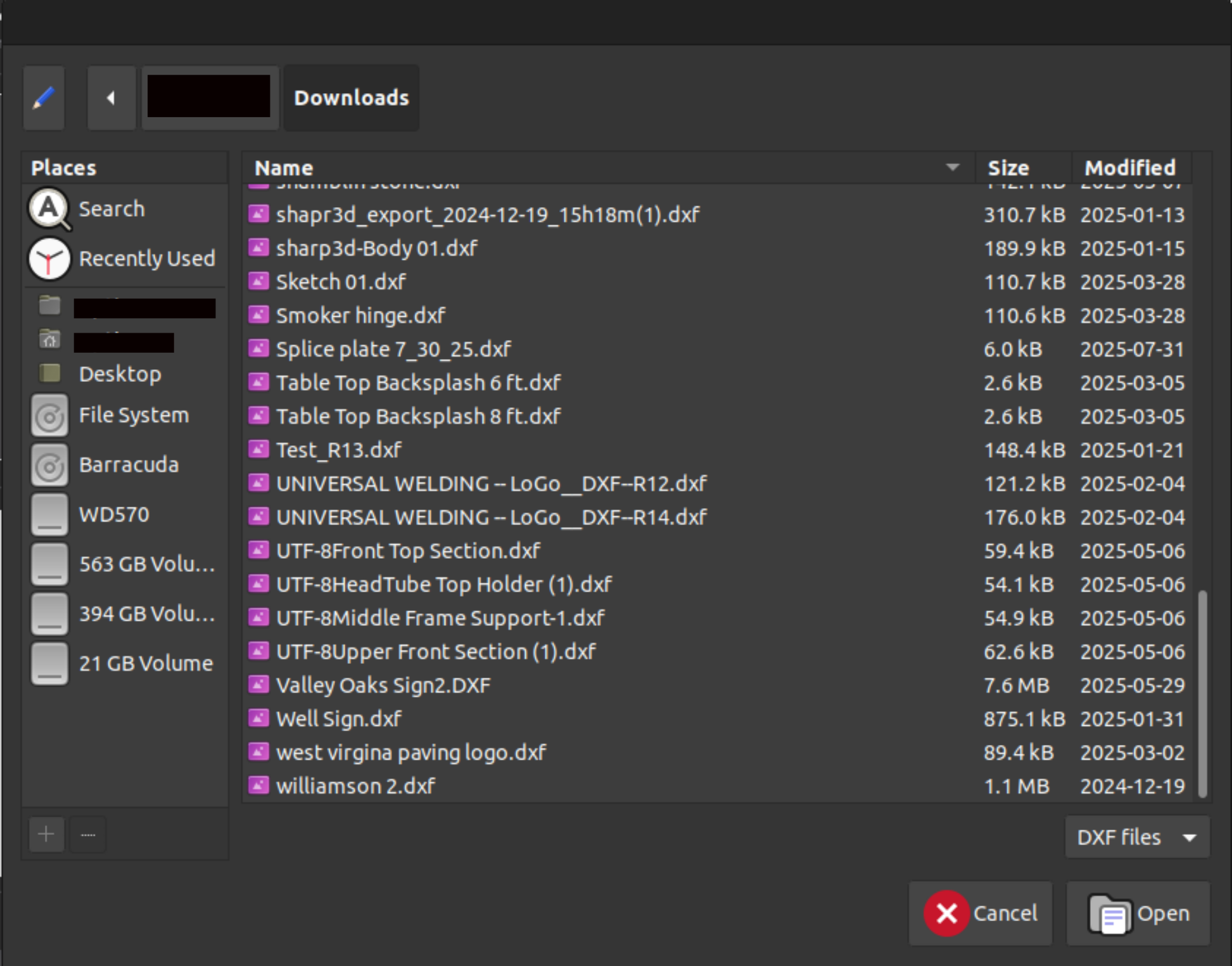
In that case, the file picker will open and the user can select the folder on their PC to import the DXF files from (similar to the Project option above, however the goal is to select a folder rather than a .ucad file):
2. Available DXF files within the selected folder:
This will list all available files that can be imported from within the chosen folde:
When adding a DXF file, its scale/size can be changed. This is done by selecting either the Scale or the Size of the file being imported. Below is an example of two files imported with different size/scale settings (1 and 2 for Scale=1 and Scale=2 respectively):
The user can also select whether the dimensions of the DXF file (which is typically unitless when created in a program such as Inkscape, etc) are to be considered to be inches or mm by default.
Note that in situations where a file needs to be scaled up/down by a factor of 25.4 (to convert from mm to inches or vice versa) it is considered best practice to do so in the Dimensions window before clicking the Add to Nest button, rather than to manually scale it after the file is already imported into the CAM module. The reason for this is due to the fact that on files that are scaled incorrectly (usually too small), fine lines and details may sometimes be lost upon import. In such a scenario, increasing the size of the file by 25.4 times after it has already been imported will not result in an increase in detail. For instance, if you are aware that a DXF file that is set to 15mm by 15mm should actually be 15” by 15”, it is best to toggle the units toggle or to scale it before Adding to Nest, rather than using the Scale button in the top ribbon (see below):
After the necessary dimensions and scaling adjustments have been performed, the file can be imported into the editor using the Add to Nest button.
Shapes Library
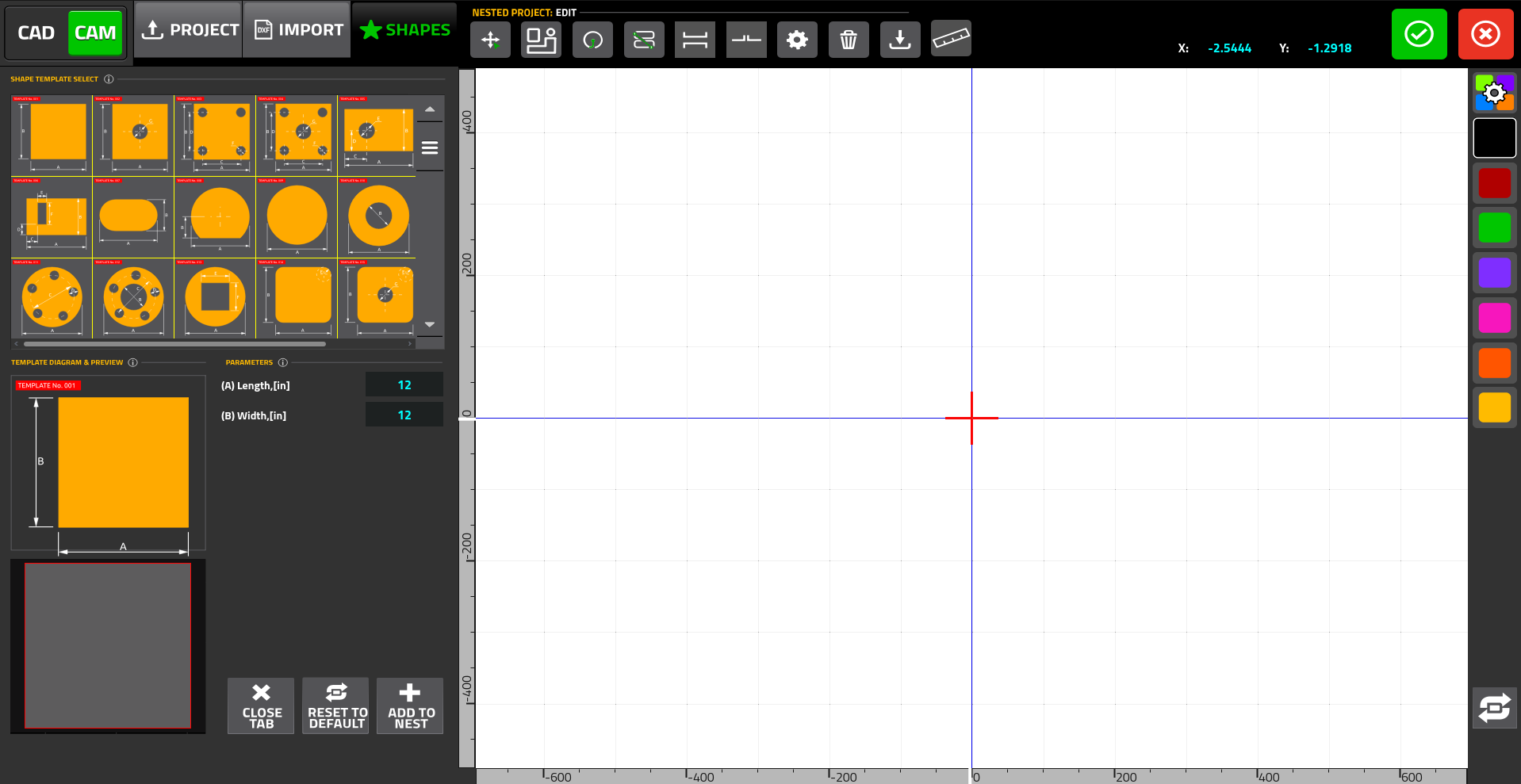
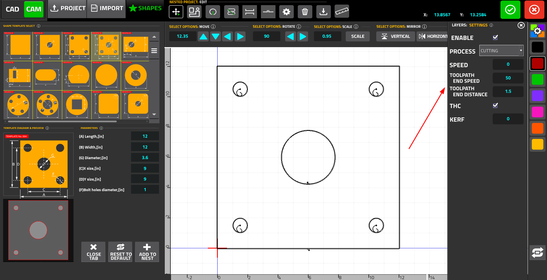
The Shapes Library allows the user to pick a shape from a built-in parts library that features common shapes (such as rectangles, trapezoids, etc), and to customize its dimensions. Upon pressing the Shapes button, the following sidebar will be opened:
This is the list of 70+ available shapes/parts that are built into myCNC software. These include common shapes such as squares, circles, trapezoids, etc.
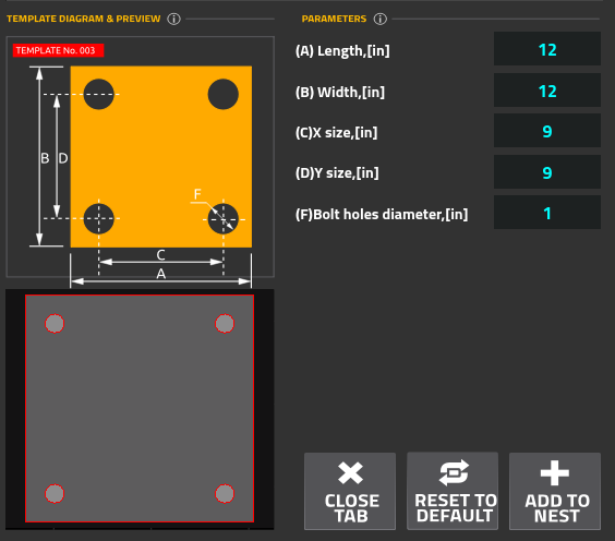
This section of the sidebar allows the user to customize the dimensions of the chosen template. Depending on the specific part, this includes the length/width of the template, bolt hole size and position, and other parameters:
After the operator has selected the necessary custom parameters for the chosen template, it can be added to the CAM editor using the Add to Nest button. Alternatively, the user can reset the parameters of the template to their default values, or close the Shapes tab.
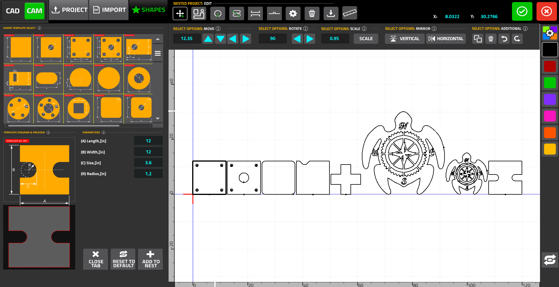
Overall, multiple files can then be imported into the software by pressing the Add to Project button for each file (regardless of whether each file is imported as an existing project, a DXF file, or a shape/template).
The imported files will then be arranged besides each other to be imported as one G-code file:
Edit imported files
Once the files have been imported into the editor, the user can then manipulate/edit them further. The following buttons are available in the top row:
- Part selection/repositioning
- Nesting
- Leads
- Cutting sequence
- Bridges (in development)
- Tabs (in development)
- Project settings
- Delete Project
- Save Project
- Ruler
The five major editing sections (highlighted in the list above) will be described in detail below.
Layer Settings
Layers allow the user to do per-contour editing of the following options:
- Enabling/disabling the contour
- Process type (Cutting/Marking/Engraving/Drilling)
- Cutting speed (this overrides the defaults specified by the cutcharts etc)
- Toolpath End Speed and Toolpath End Distance - allows to slow down the cut to a specific speed at a specific distance from the end of the cut
- THC Enable/Disable (in development, not available as of October 2025)
- Kerf for the selected contour
The layers are demarcated by the different colours available in the toolbar on the right. To assign a layer to a contour, select the colour (for instance, red) and click on the contour. It will change colour and will inherit the necessary settings upon import.
NOTE: To recalculate kerf values, press the Refresh button at the bottom of the Layers toolbar.
