Table of Contents
MyCNC Plasma Configuration Example based on profile 1024P-V2
NOTE: The myCNC team recommends utilizing the examples provided in this manual (as well as other manuals in this documentation) as a starting point for your machine setup. When possible (and applicable), it is recommended to keep changes to a mininum. In general, using these examples as the basis for your PLCs/macro commands allows for an easier setup process.
In this article, we will show an ET7 control board connection example and the software configuration to build a Middle-class Plasma/Gas cutting table. The Cutting table supposed to have
- Torch Height control (THC) width Z height control through standard Z axis (no matter stepper or servo),
- Initial Height Control (IHC) - Probe sensor and ability to find material by lowering a Torch and searching material sheet by probing.
- (Optional) Oxyfuel gas cutting torch control (Oxy Heat low/high pressure valves, Oxy Cutting high/low pressure valves, Gas valve, Ignition valve/relay)
- (Optional) Drill head - Lowering Drill valve, Drill ON relay
- (Optional) Mechanical (or Pneumatic) Scriber to perform marking operations.
Configuration process might be quite complicated, Software programming skills needed to do all this stuff. However, customers able to skip all this process and use configuration defined in the profile by default.

Power supply connection
Connect 24V DC power supply to contacts +24V and GND
Pulse-Dir connection and configuration
Connect pulse-dir outputs according to the first picture. Connection configured to use dual motors for X and Y axes. Leave motor output unconnected if you have only 1 motor for X or Y axes.
Axes configuration is shown below

Inputs connection
Arc ON, IHC sensors
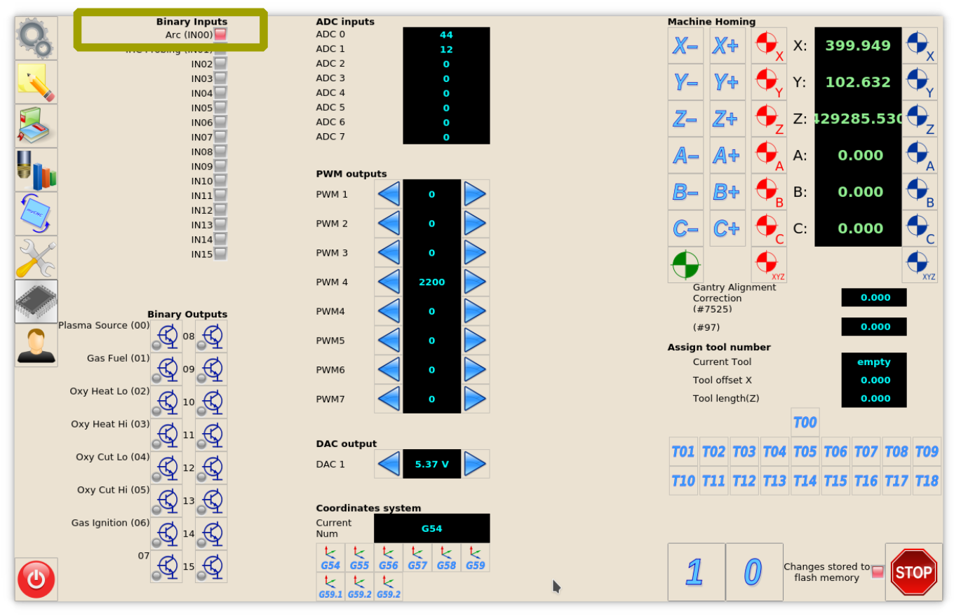
IN0 - Arc ON Sensor from plasma power source. IN1 - Initial Height Control (IHC) Sensor or Probe Sensor - a sensor which triggered when the torch touches the material sheet.
Both inputs should be configured in PLC Builder, include file pins.h
#define INPUT_ARC	0
#define INPUT_IHC	1
To see the state of both inputs on the main screen led screen items should be configured in cnc-screen-xml
<gitem type="led" where="led1-toolbar" orientation="horizontal" labelFontStyle="bold"
labelAlignment="right;vcenter" labelFontFamily="Arial" labelWidth="90"
labelFontSize="12" inversion="no" ledColor="green" width="15" height="15"
address="inputs" number="0" >
  <message>Arc Sensor</message>
  <message_ru>Дугa</message_ru>
</gitem>

<gitem type="led" where="led1-toolbar" labelFontFamily="Arial" labelWidth="90"
labelFontSize="12" labelAlignment="right;vcenter" labelFontStyle="bold"
inversion="no" ledColor="green" width="15" height="15" orientation="horizontal"
address="inputs" number="1" >
  <message>IHC Sensor</message>
  <message_ru>Касание</message_ru>
</gitem>
address="inputs" number="0" - for Arc Sensor (IN0)
address="inputs" number="1" - for IHC Probe Sensor (IN1)

Home Sensors
IN4 - Home Z
IN5 - Home X
IN6 - Home Y1
IN7 - Home Y2
The inputs should be configured in “Inputs/Sensors” - “Limits” settings dialog if Home sensors are used as Limit Switches as well If Home sensors are used as Limit switches like on the table below
| Input Number | Home Sensor | Limit Switch |
|---|---|---|
| IN6 | Y1 | -Y |
| IN5 | X | -X |
| IN4 | Z | +Z |
then setting up limit switches will be as following

If Limit switchers configured and any of it is activated, job running will be stopped and Error message showed in the centre of the main screen

Homing Macro
Home sensor numbers should be configured in Macro Wizard accordingly and Homing procedures for X, Y, Z axes generated.
Axis X - Homing X - M131

- Change setings in macro Wizard for Axis X
- Press Generate to generate Homing X macro to “macro preview” window, check the code
- Press Save Macro to save the Homing X macro to M131 file on the disk
Axis Y - Homing Y - M132

- Change setings in macro Wizard for Axis Y
- Press Generate to generate Homing Y macro to “macro preview” window, check the code
- Press Save Macro to save the Homing Y macro to M132 file on the disk
Axis Z - Homing Z - M133

- Change setings in macro Wizard for Axis Z
- Press Generate to generate Homing Z macro to “macro preview” window, check the code
- Press Save Macro to save the Homing Z macro to M133 file on the disk
Led items on the main screen should be configured in cnc-screen.xml configuration file of the profile to see a current state of Home Sensors.
<gitem type="led" where="led0-toolbar"
   orientation="horizontal" labelAlignment="right;vcenter" labelFontFamily="Arial" labelWidth="80"
   labelFontSize="12" labelFontStyle="bold" width="15" height="15"
   address="inputs" number="7" inversion="1"  ledColor="green" >
<message>Home Y1</message>
<message_tr>REF Y1</message_tr>
<message_ru>Хоум Y1</message_ru>
</gitem>
<gitem  type="led" where="led0-toolbar"
   orientation="horizontal" labelAlignment="right;vcenter" labelFontFamily="Arial"
   labelWidth="80" labelFontSize="12" labelFontStyle="bold" width="15" height="15"
   address="inputs" number="6" inversion="1" ledColor="green" >
<message>Home Y2</message>
<message_tr>REF Y2</message_tr>
<message_ru>Хоум Y2</message_ru>
</gitem>
<gitem type="led" where="led0-toolbar"
   orientation="horizontal" labelAlignment="right;vcenter" labelFontFamily="Arial" labelWidth="80"
   labelFontSize="12" labelFontStyle="bold" width="15" height="15"
   address="inputs" number="5" inversion="1" ledColor="green" >
<message>Home X</message>
<message_tr>REF X</message_tr>
<message_ru>Хоум X</message_ru>
</gitem>
<gitem type="led" where="led0-toolbar"
   orientation="horizontal" labelAlignment="right;vcenter" labelFontFamily="Arial" labelWidth="80"
   labelFontSize="12" labelFontStyle="bold" width="15" height="15"
   address="inputs" number="4" inversion="1" ledColor="green" >
<message>Home Z</message>
<message_tr>REF Z</message_tr>
<message_ru>Хоум Z</message_ru>
<message_kr>Хоум Z</message_kr>
        </gitem>
| Input Number | Home Sensor | led attributes |
|---|---|---|
| IN7 | Y2 | address=“inputs” number=“7” inversion=“1” ledColor=“green” |
| IN6 | Y1 | address=“inputs” number=“6” inversion=“1” ledColor=“green” |
| IN5 | X1 | address=“inputs” number=“5” inversion=“1” ledColor=“green” |
| IN4 | Z | address=“inputs” number=“4” inversion=“1” ledColor=“green” |

Emergency Stop button
IN15 configured as (Emergency Stop)
An emergency stop should be set up in “Inputs/Sensors” – “Alarms” setting dialog. Emergency setup is shown below

If button is pressed Job running will be stopped, new run will be blocked, Alarm message displayed on the main screen

Job Start/Stop buttons
Inputs can be used as Hot Keys. Binary inputs IN14 and IN13 can be configured as “Start” and “Stop” keys in “Panel/Pendant” “Hardkeys” settings dialog. See inputs configuration o a picture below. To configure buttons press “+” button, select input number (13 or 14), select “Pressed” checkbox and choose Slots:
- “Job: Start running” - for Start button
- “Job: Stop running” - for Stop button

Outputs
Plasma ON
Plasma On signal used to turn ON plasma power source. Relay output or Open Collector output can be used as Plasma ON output. In this profile, We have reserved 2 outputs (open collector OUT0 and relay output (relay P4) to generate Power ON signal to plasma power source.
Led to show PlasmaPower current state should be configured in cnc-screen.xml
<gitem type="led" where="led1-toolbar" orientation="horizontal"
   labelAlignment="right;vcenter" labelFontFamily="Arial" labelWidth="90"
   labelFontSize="12" labelFontStyle="bold" width="15" height="15"
   address="outputs" number="0" ledColor="red" inversion="no" >
   <message>Plasma Power</message>
   <message_ru>АПР</message_ru>
</gitem>
| Output Number | led attributes |
|---|---|
| OUT0 | address=“outputs” number=“0” inversion=“no” ledColor=“red” |

Output numbers for Plasma power source should be defined in PLC Builder, pins.h include file
- pins.h
#define OUTPUT_PLASMA1	0
#define OUTPUT_PLASMA2	15
External THC ON
In case built-in THC does not meet customer's requirements, output pin can be used to turn ON external THC. This pin can be used for ET6 control board which does not have built-in THC. In this example, we use an output OUT14 (relay P3) to turn ON/OFF external Torch Height Control (THC)
Led to show External THC state should be configured in cnc-screen.xml
<gitem type="led" where="led2-toolbar" orientation="horizontal"
    labelAlignment="right;vcenter" labelFontFamily="Arial" labelWidth="80"
    labelFontSize="12" labelFontStyle="bold" width="15" height="15"
    address="outputs" number="14" inversion="0" ledColor="blue" >
   <message>THC</message>
   <message_ru>Слежение</message_ru>
</gitem>
| Output Number | led attributes |
|---|---|
| OUT14 | address=“outputs” number=“14” inversion=“no” ledColor=“blue” |

Output numbers for external THC should be defined in PLC Builder, pins.h include file
- pins.h
#define OUTPUT_THC_EXT 14
Scriber
Optional Scriber can be used for marking operations. Scriber turned on by code M72 and turned off by M73. PLC procedures M72.plc, M73.plc should handle scriber turning ON-OFF. We use output OUT13 (relay P2) to control a scriber.
Led to show Scriber state is configured in cnc-screen.xml
<gitem type="led" where="led3-toolbar" orientation="horizontal"
    labelAlignment="right;vcenter" labelFontFamily="Arial" labelWidth="110"
    labelFontSize="12" labelFontStyle="bold" width="15" height="15"
    address="outputs" number="13" inversion="0" ledColor="yellow" >
   <message>Scriber</message>
   <message_ru>Маркировка</message_ru>
</gitem>
| Output Number | led attributes |
|---|---|
| OUT13 | address=“outputs” number=“13” inversion=“no” ledColor=“yellow” |

Output numbers for external THC should be defined in PLC Builder, pins.h include file
- pins.h
#define OUTPUT_SCRIBER 13
PLC procedures for Scriber Marking On - M72.plc
- M72.plc
#include pins.h
#include vars.h
main()
{
  timer=0;
  portset (OUTPUT_SCRIBER);
  //Wait 0.5sec till scriber ready to marking
  timer=500;do{timer--;}while(timer>0);
  exit(99);
};

PLC procedures for Scriber Marking Off - M73.plc
- M73.plc
#include pins.h
#include vars.h
main()
{
  timer=0;
  portclr(OUTPUT_SCRIBER);
  //Wait 0.5sec till scriber move to parking position
  timer=500;do{timer--;}while(timer>0);
  exit(99);
};

THC
Arc Voltage
Arc Voltage from Arc voltage divider is connected to ADC1 galvanic isolated input according to the first picture.
ADC1 channel should be configured as THC#1 feedback channel (THC#2…THC4 are reserved for Multi-Head Gas cutting machines).

There are 4 parameters to monitor THC on the main screen:
- Arc Ref - Reference Voltage for THC. THC measures actual Arc Voltage and controls torch height up and down to keep Arc Voltage equal to Reference Voltage. Reference voltage can be setup
- Manually on the main screen by operator
- From G-code
- loaded from Cutcharts
- THC can measure actual Arc voltage just after pierce finished and use it as a Reference.
- Arc Reference Adjustment - variable is used to tune cutting height on the fly by changing Arc Reference value in a small range. Global Variable #7012 is used as Reference Voltage Adjustment. The sum of Arc Reference and Arc Reference Adjustment is used as THC reference. Potentiometer or rotary encoder can be connected to Adjustment variable #7012 for convenient Torch Height tuning while plasma cutting.
- Arc Voltage - actual measured arc voltage - display item should be attached to ADC channel used as THC Feedback (that's ADC#1 in out example).
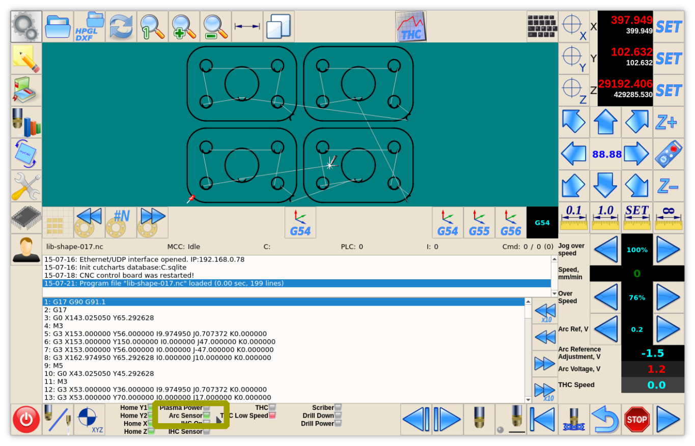
THC parameters are shown in screenshot below

Reference Voltage display
A number of Global variables represent Voltage Reference for THC
- #7011 - Reference Voltage
- #7012 - Reference Voltage Adjustment
- #7013 - A sum of #7011 and #7012 which is used as a complete THC Voltage Reference
Reference Voltage value can be changed either throgh
- Global Variable #7011 (button actions like cnc-gvariable-inc-7011, cnc-gvariable-dec-7011) or
- CNC variable 0xa3 (button actions like cnc-variable-inc-0xa3, cnc-variable-dec-0xa3).
Display Item with Increment/Decrement buttons (kspinbox) setup for Reference Voltage is shown below
<gitem type="kspinbox" where="w-operate" K="#VARC" format="%3.1f"
       action="cnc-variable-dec-0xa3;cnc-variable-inc-0xa3"  name="display-cnc-gvariable-7013"
       bgColor="black" labelWidth="60" displayWidth="60" fontStyle="bold" labelFontFamily="Arial"
       fgColor="cyan" labelFontStyle="bold" format="%3.1f" height="60"
       labelFontSize="12" orientation="horizontal">
   <message>Arc Ref, V</message>
   <message_ru>Опора дуги, В</message_ru>
</gitem>
- Action - action=“cnc-variable-dec-0xa3;cnc-variable-inc-0xa3” - to change raw Reference Voltage value
- Name - name=“display-cnc-gvariable-7013” - to display the sum of Voltage Reference and Adjustment value
- Ratio - K=“#VARC” - myCNC uses Reference Voltage in ADC units. Ratio “K” with named parameter “#VARC” is used to convert ADC units and display the value in Volts
- Format - format=“%3.1f” defines display format in C-like style
Reference Voltage Adjustment display
Simple display of Global Variable #7012 is used to show Reference Voltage Adjustment on the main screen
<gitem type="display" where="w-operate"
  name="display-cnc-gvariable-7012" K="#VARC" format="%3.1f" height="30"
  fontSize="20" fgColor="cyan" labelFontFamily="Arial" labelFontSize="12" labelFontStyle="bold"
  bgColor="black" labelWidth="120" displayWidth="120" fontStyle="bold" orientation="horizontal">
  <message>Arc Reference Adjustment, V</message>
  <message_pl>Korekta napięcia, V</message_pl>
  <message_ru>Подстройка опоры дуги, В</message_ru>
</gitem>
- Name - name=“display-cnc-gvariable-7012” - to display Voltage Reference Adjustment value
- Ratio - K=“#VARC” - myCNC uses Reference Voltage Adjustment in ADC units. Ratio “K” with named parameter “#VARC” is used to convert ADC units and display the value in Volts
- Format - format=“%3.1f” defines display format in C-like style
Arc Voltage display
Simple display of ADC input which is used as THC Feedback channel (ADC#1 in our example).
<gitem where="w-operate" type="display"
   address="adc-inputs" number="1" K="#VARC" format="%5.1f"
   bgColor="#202020" labelFontFamily="Arial"  fgColor="red" labelFontStyle="bold"
   height="30" displayWidth="120" labelWidth="120" fontStyle="bold"  fontSize="20"
   labelFontSize="12" orientation="horizontal">
   <message>Arc Voltage, V</message>
   <message_ru>Напряжение дуги, В</message_ru>
</gitem>
- Type - type=“display” - defines “display” item.
- Address - address=“adc-inputs” - set up the display to show one of ADC inputs value
- Number - number=“1” - set up the display to show ADC1 value
- Ratio - K=“#VARC” - convert ADC units to Volts
- Format - format=“%3.1f” defines display format in C-like style
Plasma Cutting Start/Stop Procedures
We offer to use M71 code as Start Cutting and M74 code as Stop Cutting. Codes M03/M05 are widely used to Cutting on and off also. We recommend to use this codes however any other codes can be selected and PLC procedures created and compiled in PLC Builder.
Plasma Cutting Start
A procedure for start plasma cutting is
- Probe material sheet (move Torch down till probe sensor pressed)
- Move Torch up to Ignition Height
- Turn Plasma Power ON, wait Arc ON sensor ready
- Move up to Pierce Height
- Wait Pierce Time
- Move down to Cutting Height
- Start Torch Height Control (THC)
- Start XY motion
M71/M03 procedure handles all this sequence, no extra programming needed in g-code

Code for Plasma Cutting start shown below
- M71.plc
#include pins.h
#include func_ihc.h
#include vars.h

main()
{
   timeout_plasma_ready=10000;
   timer=0;

   do_plasma_probe();
   do_move_ignition_height();

   portset(OUTPUT_PLASMA1);
   portset(OUTPUT_PLASMA2);

   timer=5000; //wait up to 5secs till plasma arc ready
   do{
    timer--;
    a=portget(INPUT_ARC);
    if (a!=0) { timer=0; };
   }while(timer>0); //pause

//doublecheck arc sensor
   a=portget(INPUT_ARC);
   if (a==0)
   {
   message=PLCCMD_TRIGGER2_ON;
   texit=timer+10;do{timer++;}while(timer<texit);
   exit(plc_exit_plasma_fail);
   };

   do_move_pierce_height();
   timer=ihc_pierce_time;
   do{timer--;}while(timer>0);

   do_move_cutting_height();

   //start_thc();
   if (thc_enabled!=0)
   {
    //start THC control
    gvarset(7570,thc_avc_start);	//THC #0 ON
    };


   //set OK message and exit
   proc=plc_proc_plasma;

   message=PLCCMD_TRIGGER1_ON;
   timer=2;do{timer--;}while(timer>0);

   message=PLCCMD_TRIGGER2_ON;
   timer=2;do{timer--;}while(timer>0);


   //set OK message and exit
   message=PLC_MESSAGE_PLASMA_OK;
   exit(99);
};
Functions do_plasma_probe, do_move_ignition_height, do_move_pierce_height, do_move_cutting_height are defined in “func_ihc.h” include file
- func_ihc.h
/ start motion //flags
//  bit 0 - absolute programming
//  bit 1 - machine coordinates
//  bit 7 - delayed start.
//axes mask
//  bit 0 - X axis
//  bit 1 - Y axis
//  bit 2 - Z axis
//  bit 3 - A axis
//  bit 4 - B axis
//  bit 5 - C axis

do_plasma_probe()
{
  gvarset(7080,ihc_move_down_speed);//seet speed;
  if (ihc_enabled!=0)
  {
    message=PLCCMD_TRIGGER2_OFF;
    texit=timer+5;do{timer++;}while(timer<texit);

    portset(OUTPUT_PROBE);
    timer=200; do{ timer--; }while (timer>0);

    sens=portget(INPUT_IHC);
    if (sens==0)
    {
    g0moveA(0x0,0x4,0-30000);//Z axis,
    timer=200; do{timer--;}while(timer>0);//wait till motion started

    do
    {
      code=gvarget(6060);
      sens=portget(INPUT_IHC);
      if (sens!=0)
      {
       code=1;
       message=PLCCMD_LINE_STOP;//skip line
      };
      }while (code==0);
      do { code=gvarget(6060); }while(code!=0x4d);//wait till motion finished
    };
  };
  portclr(OUTPUT_PROBE);
};

do_move_ignition_height()
{
  gvarset(7080,3000);//seet speed;
  if (ihc_enabled!=0)
  {
    ihc_current_height=ihc_correction_height+ihc_ignition_height;
    if (ihc_current_height>5)
    {
      g0moveA(0x0,0x4,ihc_current_height);//Z axis, ignition_height
      timer=200;do{timer--;}while(timer>0);//wait till motion started
      do { code=gvarget(6060); }while(code!=0x4d);//wait till motion finished
    };
  };
};


do_move_pierce_height()
{
  ihc_current_height=ihc_pierce_height-ihc_ignition_height;
  if (ihc_current_height>5)
  {
    g0moveA(0x0,0x4,ihc_current_height);//Z axis, pierce_height
    timer=200;do{timer--;}while(timer>0);//wait till motion started
    do { code=gvarget(6060); }while(code!=0x4d);//wait till motion finished
  };
};

do_move_cutting_height()
{
  ihc_current_height=ihc_cutting_height-ihc_pierce_height;
  if (ihc_current_height<(0-5))
  {
    g0moveA(0x0,0x4,ihc_current_height);//Z axis, cutting_height
    timer=200;do{timer--;}while(timer>0);//wait till motion started
    do { code=gvarget(6060); }while(code!=0x4d);//wait till motion finished
  };
};
How to disable Arc ON input
It is highly recommended to use Arc ON signal from Plasma power source and connect it to ET7 controller Arc ON input to get correct feedback about current plasma state. Cutting will be started just after Arc Plasma ready and stopped in case of plasma fail.
However Arc ON signal can be disabled in case you don't want to use it.
There is 3 simple methods how to do it. You can use any of it.
- (Method 1) Just short Arc ON input on ET7 control board. To do it you need
- Short J1 to power up binary inputs IN0…IN3
- Connect IN0 pin to GND (any of GND pins can be used, please see photo as an example)
- Check on-board LED correspondant to IN0 is ON

- check if software LED on Diagnose widget is activated
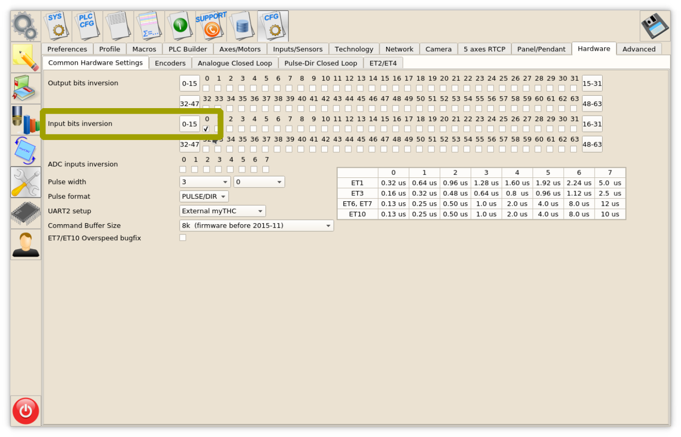
- (Method 2) Invert Binary input #0 in Common Hardware Settings dialog, then check it on Diagnose widget or in the main screen
- (Method 3) Remove the following pieces of code for the M71.plc source, then save, rebuild and send the binary files (press 3 buttons on the right of PLC Builder screen.


timer=5000; //wait up to 5secs till plasma arc ready
do{
  timer--;
  a=portget(INPUT_ARC);
  if (a!=0) { timer=0; };
}while(timer>0); //pause

//doublecheck arc sensor
a=portget(INPUT_ARC);
if (a==0)
{
  message=PLCCMD_TRIGGER2_ON;
  texit=timer+10;do{timer++;}while(timer<texit);
  exit(plc_exit_plasma_fail);
};
and
message=PLCCMD_TRIGGER1_ON; timer=2;do{timer--;}while(timer>0);